
Selective four wheel drive transmission for all-terrain vehicle

a four-wheel drive transmission and all-terrain technology, applied in the direction of vehicle components, control devices, transportation and packaging, etc., can solve the problems of increased weight to the vehicle, complicated structure of the drive system, and distinct disadvantages of the increase in weigh

Inactive Publication Date: 2001-08-16
YAMAHA MOTOR CO LTD
View PDF0 Cites 27 Cited by
  • Summary
  • Abstract
  • Description
  • Claims
  • Application Information

AI Technical Summary

Problems solved by technology

Such shiftable drive systems involve complicated structures and many interlocking components.
The components must be supported by the vehicle undercarriage, or frame, and necessarily result in increased weight to the vehicle.
The increased weight is a distinct disadvantage.
Additionally, positioning the shifting system at a location between the selectively-driven differential and the drive shaft can reduce the integrity of the drive train.
This reduced integrity is partially a result of the added components and numerous universal joints required to flexibly couple the drive shaft and the differential input shaft.

Method used


Image

  • Selective four wheel drive transmission for all-terrain vehicle
  • Selective four wheel drive transmission for all-terrain vehicle
  • Selective four wheel drive transmission for all-terrain vehicle

Examples


Embodiment Construction

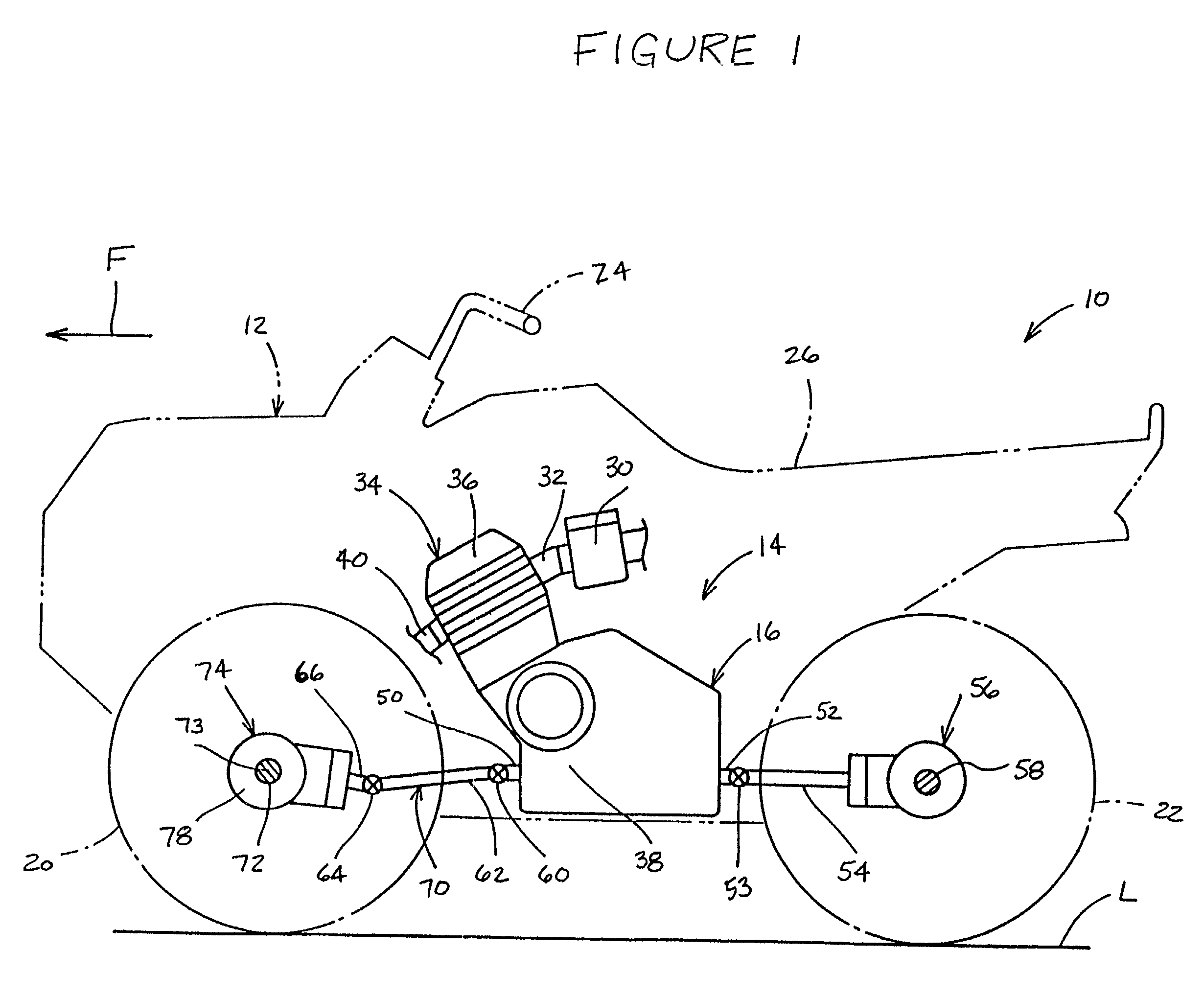
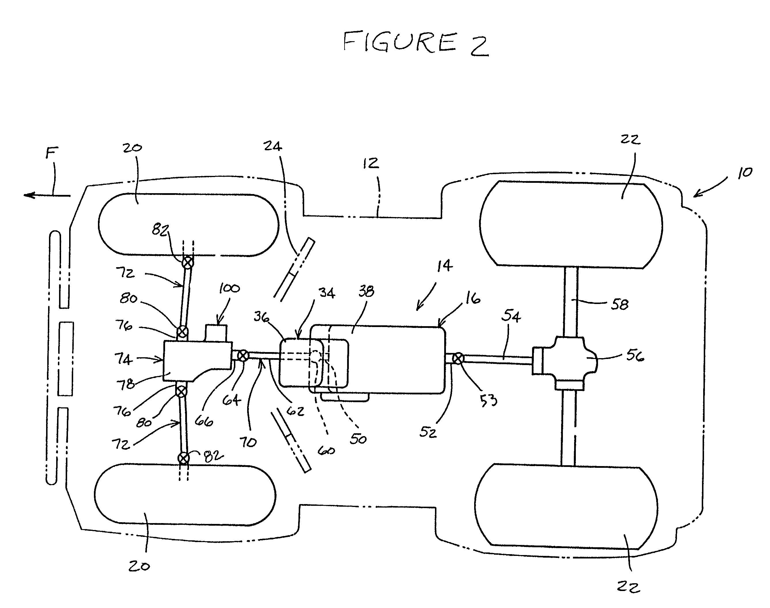
[0014] With reference to FIGS. 1 and 2, schematic illustrations of a motor vehicle, indicated generally by reference numeral 10, are presented. The illustrated motor vehicle is a four wheel all-terrain vehicle; however, as will be appreciated by those of skill in the art, the illustrated motor vehicle is purely exemplary and various features, aspects and advantages of the present transmission may find utility in a number of other vehicle applications. The motor vehicle 10 is generally comprised of a body 12, an engine 14 and a transmission 16.

[0015] The body 12 is supported by a frame (not shown). The frame carries a pair of front wheels 20 and a pair of rear wheels 22 in a known manner. The motor vehicle moves along the ground surface L on these wheels 20, 22. The body also has a steering handle 24, which is connected to the front wheels 20 in a known manner for steering the motor vehicle 10. Controls and gauges may be mounted on or around the steering handle 24. Rearward of the st...


PUM


Abstract

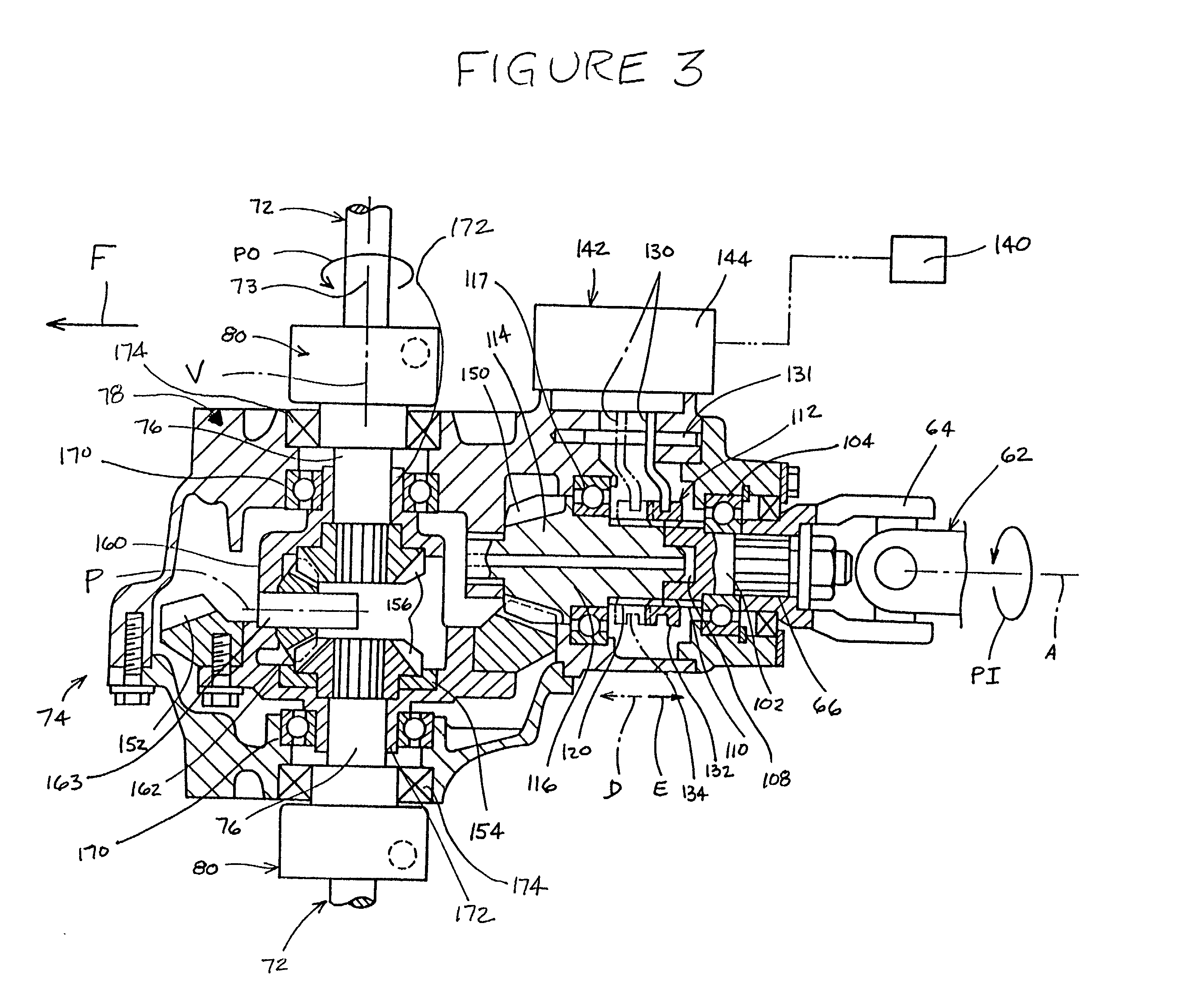
An all-terrain vehicle has a selectively engageable four wheel drive system. The system has dedicated rear wheel drive and selectively engageable front wheel drive. The front wheel drive is engaged within the differential housing. A differential input shaft extends into the differential housing. A stub shaft is journaled for rotation within the housing. A sleeve slides relative to the two shafts and couples the two through a coupling configuration. The coupling configuration results from the externally splined ends of the two shafts and the internally splined surface of the sleeve. The positioning of the sleeve is controlled by a shift fork. The shift fork is moved by an actuator in response to a signal produced by a control unit. A switch allows an operator to instruct the control unit when to engage and disengage the front wheel drive system.

Description

[0001] 1. Field of the Invention[0002] The present invention generally relates to a drive train for an all-terrain vehicle. More particularly, the present invention relates to a mechanism for selectively engaging a front wheel drive of such a vehicle.[0003] 2. Description of Related Art[0004] All-terrain vehicles are commonly equipped with two wheel drive and four wheel drive systems. In the latter type a shifting system may be provided that allows an operator to selectively engage the wheels that are not continuously driven with a drive shaft. Such a shifting system traditionally uses a mechanism located along the respective drive shaft between the associated differential gear and the transfer case. Thus, the shifting system selectively couples the drive shaft and an input shaft of the selectively-driven differential.[0005] Such shiftable drive systems involve complicated structures and many interlocking components. The components must be supported by the vehicle undercarriage, or ...

Claims


Application Information

Patent Timeline
Patent Type & Authority Applications(United States)
IPC IPC(8): B60K23/08
CPCB60K23/08
Inventor IZUMI, KAZUHIKOTAKAHASHI, KATSUSHI
Owner YAMAHA MOTOR CO LTD
Learn More