Electroplated grinding wheel and its production equipment and method

Inactive Publication Date: 2001-08-16
MITSUBISHI MATERIALS CORP
View PDF3 Cites 5 Cited by
  • Summary
  • Abstract
  • Description
  • Claims
  • Application Information

AI Technical Summary

Benefits of technology

0007] The object of this invention is to offer the electroplated grinding wheel, which has sharp grinding performance and a prolonged tool life, in view of the above mentioned conditions.
0008] Moreover, the other purpose

Problems solved by technology

Therefore, there is a fault that scratches are occurred on a work material, or the grinding precision is fallen at the grinding time.
Moreover, there also is a fault that the life of said grinding stone is shortened, since the edge par

Method used


Image

  • Electroplated grinding wheel and its production equipment and method
  • Electroplated grinding wheel and its production equipment and method
  • Electroplated grinding wheel and its production equipment and method

Examples


Example

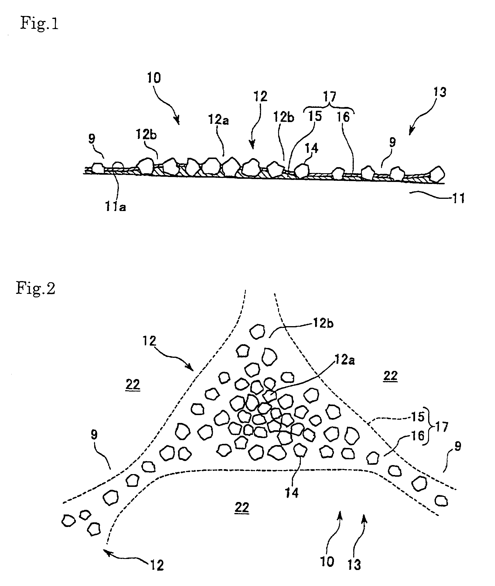
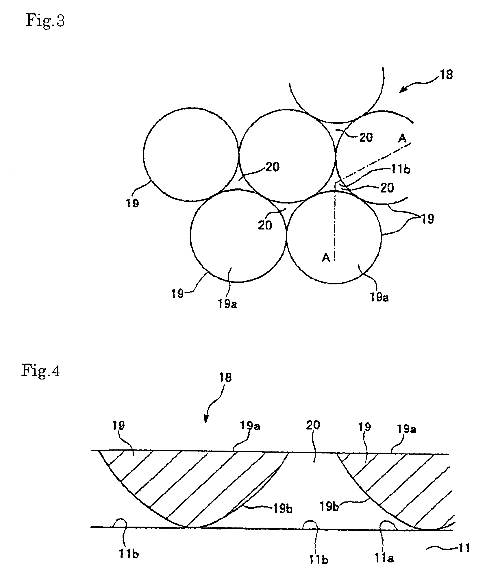
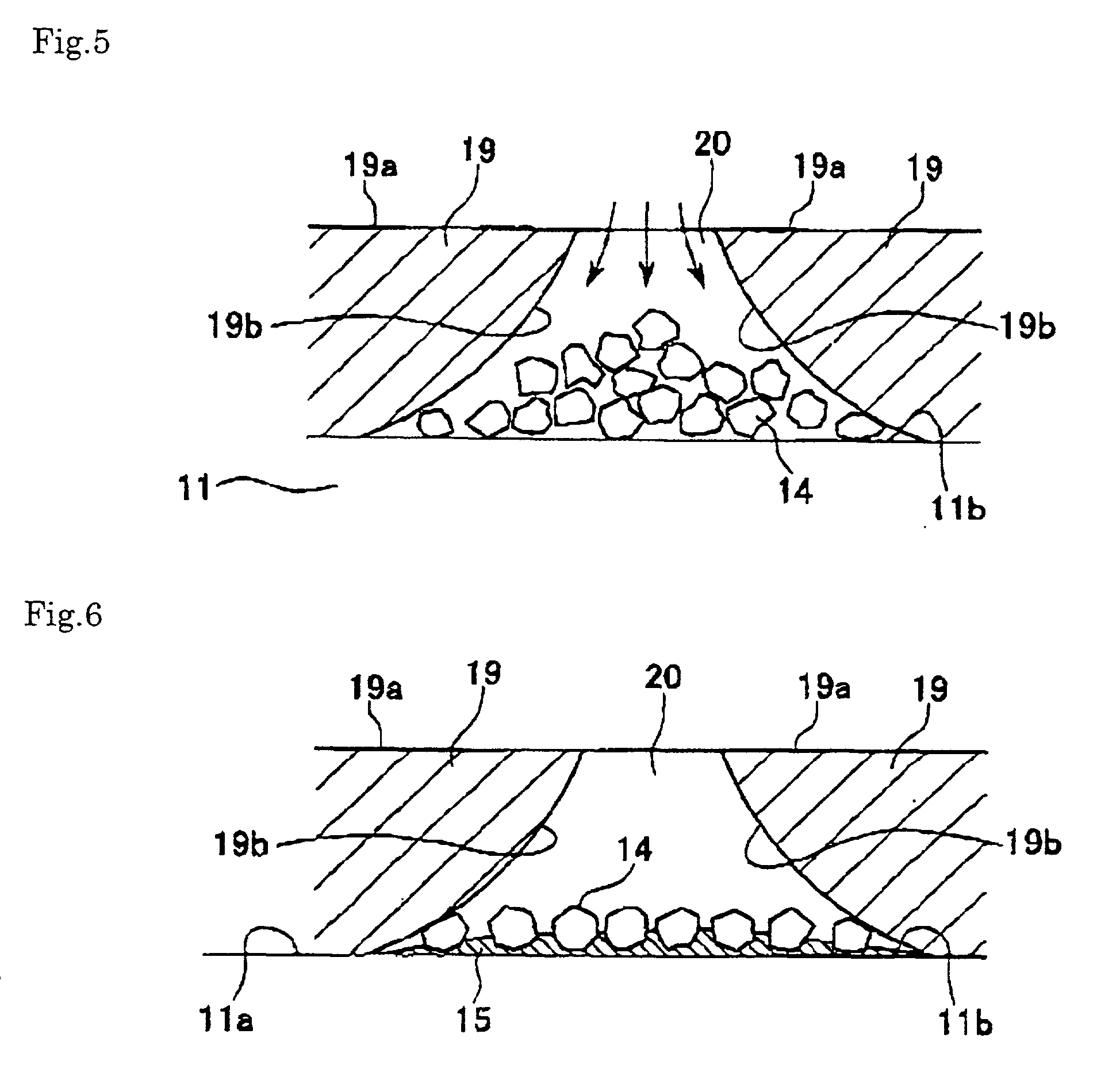
[0035] Hereafter, the example of this invention is explained with the appending drawings. FIGS. 1 to 7 is related with the 1st Example. FIG. 1 is the partial longitudinal sectional plane of the electroplated grinding wheel, and FIG. 2 is the floor plane of the electroplated grinding wheel in FIG. 1, and FIGS. 3 to 7 are the production method of the electroplated grinding wheel. FIG. 3 is the partial floor plane in the state that the masking component was set on the grinding stone substrate. FIG. 4 is the A-A line sectional plane of FIG. 3. FIG. 5 is the drawing showing the state that the super abrasive grains were dropped on the non masking area. FIG. 6 is the vertical section showing the state that the super abrasive grains were fixed with the metal plating. FIG. 7(a) is the figure showing the current distribution of the non masking area. FIG. 7(b) is the drawing showing the thickness distribution of the deposited metal with the metal plating, according to the current distribution....


PUM


Abstract

Objectives: To improve the cutting sharpness and life while the manufacturing cost is being lowered. Solution mechanism: The whetstone particle layer (13), which consists of multiple whetstone particle layer units (12), . . . , is configured on the surface (11a) of the whetstone substrate (11) while the respective whetstone particle layer units (12) are being mutually linked via the bridge unit (9). The non-whetstone particle unit (22) is configured between [adjacent] whetstone particle layer units (12) and (12). [Each] whetstone particle layer unit (12) is obtained by configuring the superwhetstone particles (14) densely in the central unit (12a) and by configuring them sparsely in the peripheral unit (12b). The metal coupling phase (17), to which the superwhetstone particles (14) are fixed, is formed by the first and second metal plate phases (15) and (16), respectively. The thickness of the first metal plate phase (15) decreases from the central unit (12a) toward the peripheral unit (12b) in the shape of a mountain.

Description

[0001] This invention relates to an electroplated grinding wheel, its production method and equipment.DESCRIPTION OF THE BACKGROUND[0002] Conventionally, when a requested formed abrasive grain layer is formed by electroplating on a grinding wheel substrate (base metal) with use of a masking component, an electroplating method is mainly used as the production method of the electroplated grinding wheel. For example, the said method is done as follows.[0003] First, as shown in FIG. 13, the surface 1a of the grinding-wheel substrate (base metal) 1, is masked by the masking component 2, excepting the area which should form the desired abrasive grain layer, and said grinding-wheel substrate 1 is dipped in the electroplating liquid with arranging the surface 1a upward.[0004] Next, the super abrasive grains 3 are sprinkled on the non masking area 1b of the surface 1a. In addition, the super abrasive grains 3 are fixed by depositing the metal plating layer 4 by passing current between the su...

Claims


Application Information

Patent Timeline
IPC IPC(8): B24D3/06B24D7/14B24D18/00
CPCB24D3/06B24D7/14B24D18/0018
Inventor TAKAHASHI, TSUTOMUSHIMOMAE, NAOKIHATA, HANAKO
Owner MITSUBISHI MATERIALS CORP
Why Eureka
Try Eureka