Digital VTR and video recording / reproducing apparatus

Inactive Publication Date: 2001-08-23
SANYO ELECTRIC CO LTD
View PDF2 Cites 5 Cited by
  • Summary
  • Abstract
  • Description
  • Claims
  • Application Information

AI Technical Summary

Problems solved by technology

In such a digital VTR, it is difficult to feed the magnetic tape at a speed higher than a normal reproduction speed to perform reproduction, that is, perform fast-forward play (including fast-backward play).
When such a phenomenon occurs at the time of recording, data corresponding to one block which have been read out of the magnetic tape cannot be recorded on the memory at the time of reproduction, so that norma

Method used


Image

  • Digital VTR and video recording / reproducing apparatus
  • Digital VTR and video recording / reproducing apparatus
  • Digital VTR and video recording / reproducing apparatus

Examples


Embodiment Construction

[0056] Description is made of an embodiment in a case where the present invention is applied to a digital VTR used for a monitoring system.

[0057] [1] Description of Configuration of Digital VTR

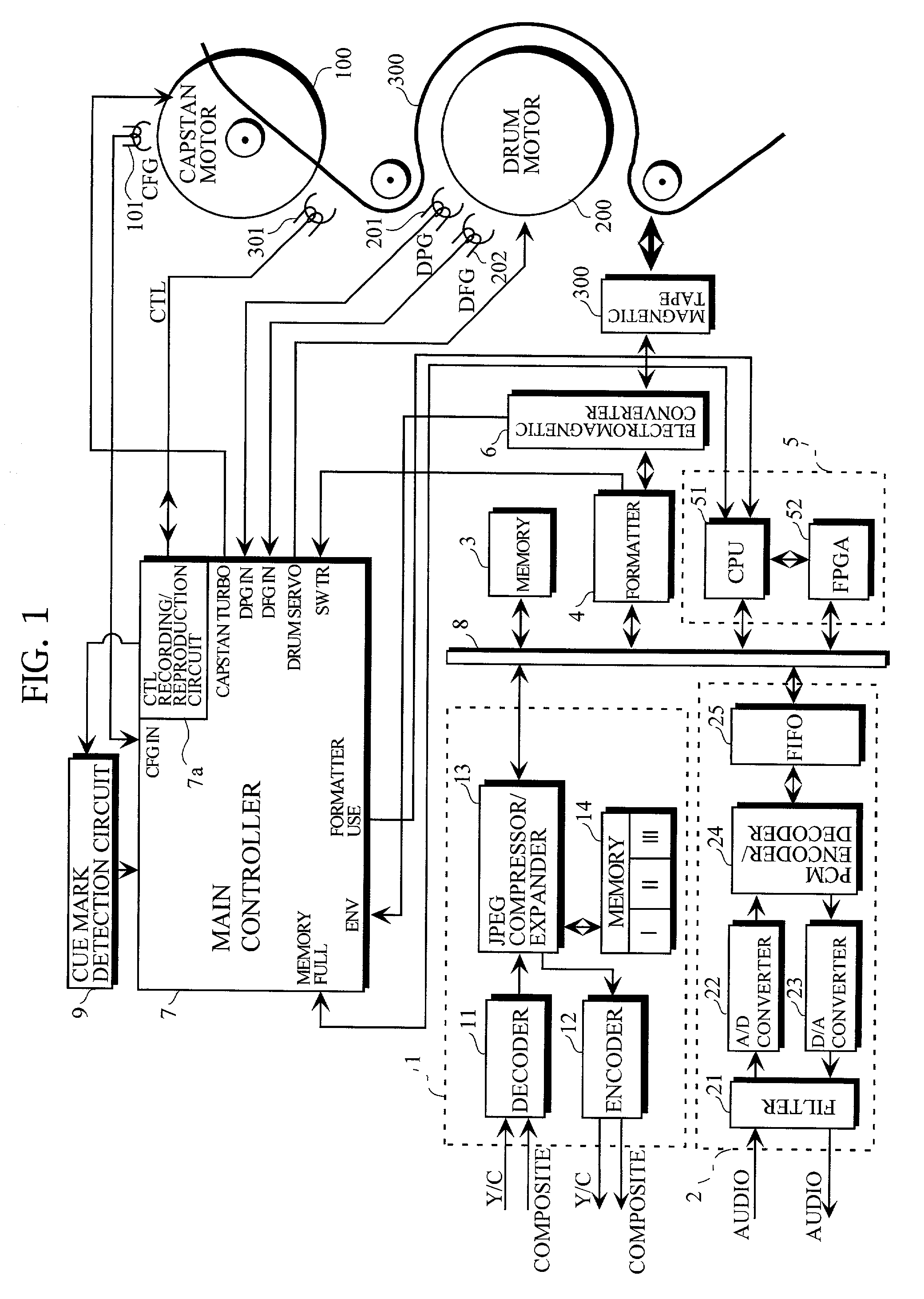
[0058] FIG. 1 illustrates the configuration of a digital VTR.

[0059] The digital VTR comprises a video processor 1, an audio processor 2, a memory 3, a formatter 4, a sub-controller 5, an electromagnetic converter 6, a main controller 7, a cue mark detection circuit 9, and so forth.

[0060] The main controller 7 is composed of a microcomputer, and comprises the function of a system controller and the function of a servo block. The main controller 7 controls a capstan motor 100 on the basis of an output of a capstan frequency generator (CFG) 101, a control signal (a CTL signal), and so forth, and controls a drum motor 200 on the basis of an output of a drum phase generator (DPG) 201, an output of a drum frequency generator (DFG) 202, and so forth.

[0061] A CTL recording / reproduction circuit 7a in t...


PUM


Abstract

Disclosed is a digital VTR comprising means for recording a cue mark in a position, corresponding to a predetermined position in the middle of each recording block, on a control track of a magnetic tape at the time of recording, means for stopping, at the time point where actual data in the recording block are stored in predetermined amounts in a memory, the acceptance of the data in the memory and accelerating a capstan motor at the time of fast-forward play, and means for decelerating the capstan motor when the cue mark is detected.

Description

[0001] 1. Field of the Invention[0002] The present invention relates generally to a digital VTR (Video Tape Recorder) for intermittently recording an input image. The present invention further relates to a video recording / reproducing apparatus such as a digital VTR.[0003] 2. Description of the Prior Art[0004] [1] A digital VTR for storing in a memory actual data (input video / audio data or its compressed data) and recording, every time data for each block are stored, the data for the block on a magnetic tape at the time of recording, while intermittently reading out the data recorded on the magnetic tape for the block, storing in the memory the data read out of the magnetic tape, reading out the data stored in the memory, and reproducing and outputting the read data at the time of reproduction has been known.[0005] In such a digital VTR, it is difficult to feed the magnetic tape at a speed higher than a normal reproduction speed to perform reproduction, that is, perform fast-forward ...

Claims


Application Information

Patent Timeline
IPC IPC(8): G11B5/008G11B15/087G11B15/18G11B15/467G11B15/52G11B20/12G11B27/00G11B27/10G11B27/32H04N5/77H04N5/783H04N9/804H04N9/806
CPCG11B5/0086G11B15/087G11B15/1875G11B15/4673G11B15/52G11B20/1207G11B27/005G11B27/107G11B27/324G11B2220/90G11B2220/91H04N5/77H04N5/783H04N9/8047H04N9/8063
Inventor OKUTANI, AYUMUHIROSE, YOSHIKIYAMASAKI, AKIRAYABUMOTO, TETSUROMIYATA, KAZUNORI
Owner SANYO ELECTRIC CO LTD
Why Eureka
Try Eureka