Fault indicator state identification method and fault indicator state identification device

A fault indicator and state recognition technology, applied in the field of image recognition, can solve the problems of high labor intensity, cumbersome and complicated methods, etc., and achieve the effect of reducing the difficulty of work

Inactive Publication Date: 2016-01-20
WILLFAR INFORMATION TECH CO LTD
View PDF3 Cites 10 Cited by
  • Summary
  • Abstract
  • Description
  • Claims
  • Application Information

AI Technical Summary

Problems solved by technology

The manual detection method is extremely cumbersome and complicated, and labor-intensive and heavy workload. In addition, the installation position of individual fault indicators is not convenient for manual judgment, which increases the difficulty and workload of manual judgment.

Method used


Image

  • Fault indicator state identification method and fault indicator state identification device
  • Fault indicator state identification method and fault indicator state identification device
  • Fault indicator state identification method and fault indicator state identification device

Examples


Embodiment Construction

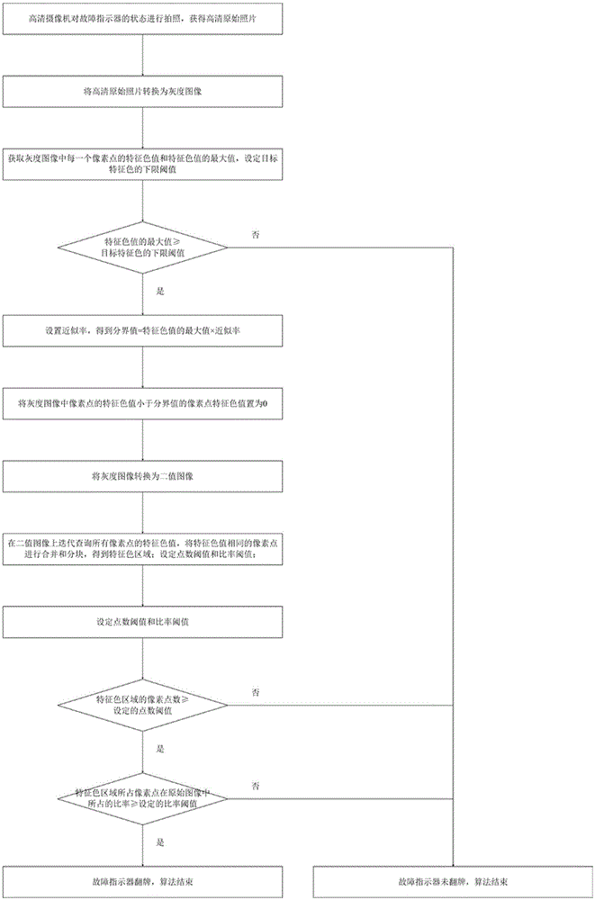
[0032] Such as Figure 1~Figure 2 Shown is the schematic flow chart of the method of the present invention and the schematic diagram of binary image:

[0033] The fault indicator state identification method provided by the present invention specifically includes the following steps:

[0034] S1 high-definition camera takes pictures of the state of the fault indicator, and obtains high-definition original photos of the state of the fault indicator;

[0035] S2 converts the high-definition original photo obtained in step S1 into a grayscale image by using a bicubic interpolation algorithm;

[0036] S3 obtains the characteristic color value of each pixel in the grayscale image, and selects the maximum value of the characteristic color value, and sets the lower limit threshold of the target characteristic color;

[0037] In order to determine whether the fault indicator has flopped, the target characteristic color is set to the color of the fault indicator after the flop, which ...


PUM


Abstract

The invention discloses a fault indicator state identification method which comprises the steps of obtaining an original picture of the fault indicator and converting the original picture to a gray scale image; preliminarily determining the state of the fault indicator according to a relationship between a characteristic color value of a gray scale image pixel point and a lower limit threshold value; converting the gray scale image to a binary image; combining pixel points and dividing into blocks on the binary image, thereby obtaining characteristic color areas; and determining the draw state of the fault indicator according to each characteristic color area. The invention further discloses a fault indicator state identification device in which the fault indicator state identification method is used. The fault indicator state identification device comprises a miniature network camera, a network switch and a computer. The miniature network camera, the network switch and the computer are connected through netting wires. According to the fault indicator state identification method, the state picture of the fault indicator is compressed, processed and identified by means of image processing technology, and therefore the draw state of the fault indicator can be automatically identified, thereby preventing manual recording and determination and reducing operation difficulty, operation difficulty and workload of personnel.

Description

technical field [0001] The invention relates to the field of image recognition, in particular to a fault indicator state recognition method and device. Background technique [0002] With the development of automation technology, the automatic operation of distribution network has become more and more important. Fault location is one of the key technologies of distribution automation. It requires the ability to quickly locate the fault point when a fault occurs, and notify the maintenance personnel of the power department in time to save time for the maintenance personnel of the power department to troubleshoot faults and restore power supply. [0003] At present, the method of fault location is to install fault indicators on the distribution network lines of the power grid. The fault indicator is equipped with a card turner. When the line is running normally, the card turner does not act, the indicator light on the indicator does not flash, and the distribution line is in a...

Claims


Application Information

Patent Timeline
Patent Type & Authority Applications(China)
IPC IPC(8): G06K9/00
CPCG06V20/00
Inventor 张义高意阳武黄雄凯许健文江林李君周到许斌
Owner WILLFAR INFORMATION TECH CO LTD
Why Eureka
Try Eureka