Focus control apparatus and focus control method

a technology of focus control and control apparatus, which is applied in the field of focus control apparatus and focus control method, can solve the problems of unresolved problem of recording unfocused footage, and achieve the effect of preventing the recording of defocused video footag

Inactive Publication Date: 2009-05-28
SONY CORP
View PDF9 Cites 9 Cited by
  • Summary
  • Abstract
  • Description
  • Claims
  • Application Information

AI Technical Summary

Benefits of technology

[0009]In contrast, in the present invention it is desirable to provide technology to be implemented in a system for recording video footage, wherein the recording of unfocused video footage that accompanies in-focus point search using a hill climbing technique in particular is prevented.
[0016]By using a deformable mirror as described above, it is possible to separately read an image signal in a focused state (i.e., during the first image reading period) and an image signal used to find an in-focus point (i.e., during the second image reading period). Consequently, the image signal read during the second image reading period may be used exclusively for in-focus point search, while the image signal read during the first image reading period may be used exclusively for recording footage. In so doing, it becomes possible to prevent recording defocused footage occurring because the focal point is being varied as part of an in-focus point search process that implements a hill climbing technique, for example.
[0017]According to an embodiment of the present invention, the recording of defocused video footage that accompanies in-focus point search is prevented in a system that records video footage as a result of separating the reading of the image signal by switching between the respective focus drive states of a first image reading period and a second image reading period. Moreover, the recording of defocused video footage is prevented even in the case where such a system implements a hill climbing technique for in-focus point search.

Problems solved by technology

However, even when the technology disclosed in the above JP-A-2004-170637 is applied to a video camera apparatus, the problem of recording unfocused footage is not resolved, due to the implementation of a hill climbing technique as the technique for in-focus point search.

Method used


Image

  • Focus control apparatus and focus control method
  • Focus control apparatus and focus control method
  • Focus control apparatus and focus control method

Examples


first embodiment

(Internal Configuration of the Imaging Apparatus)

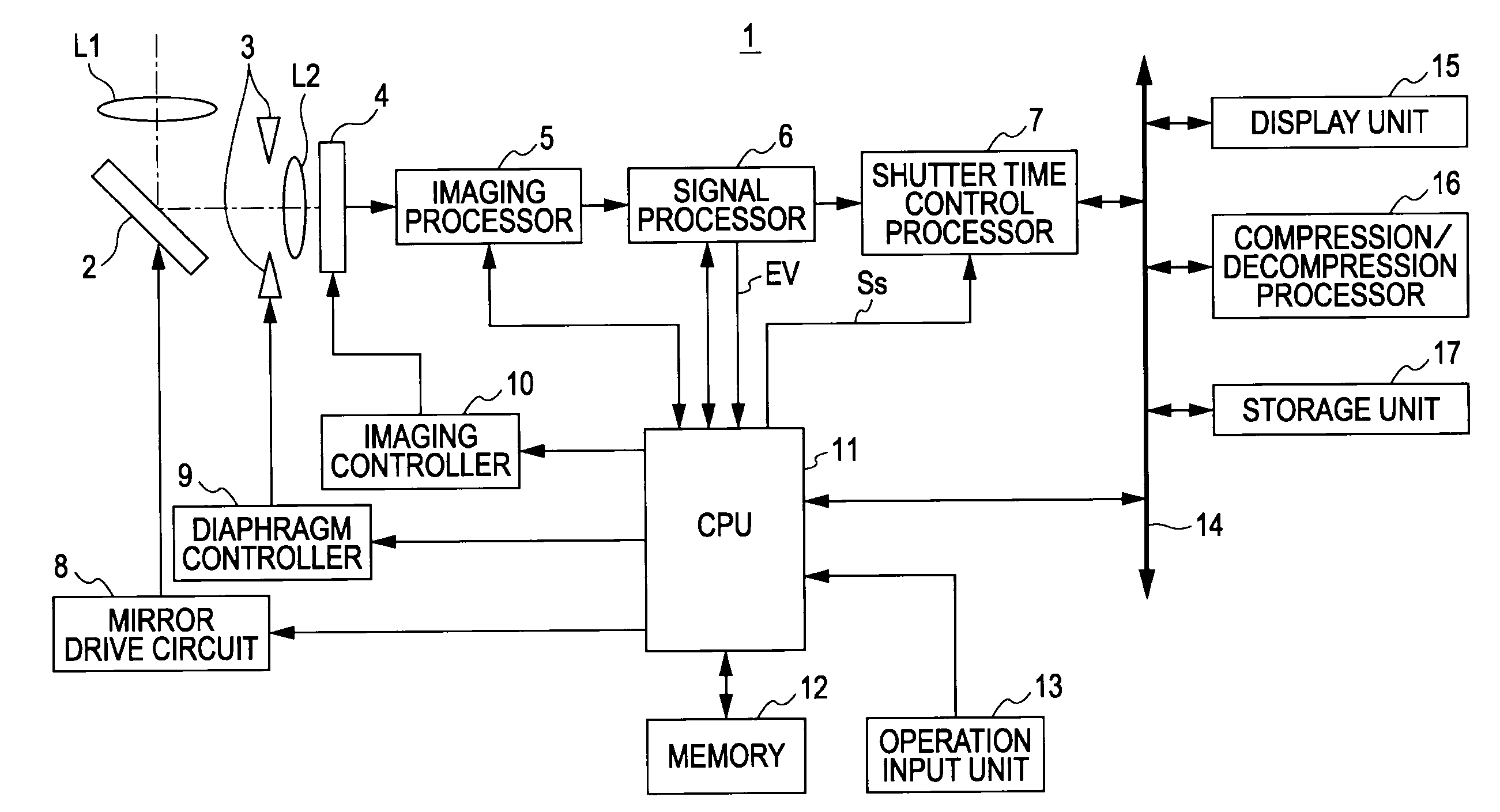
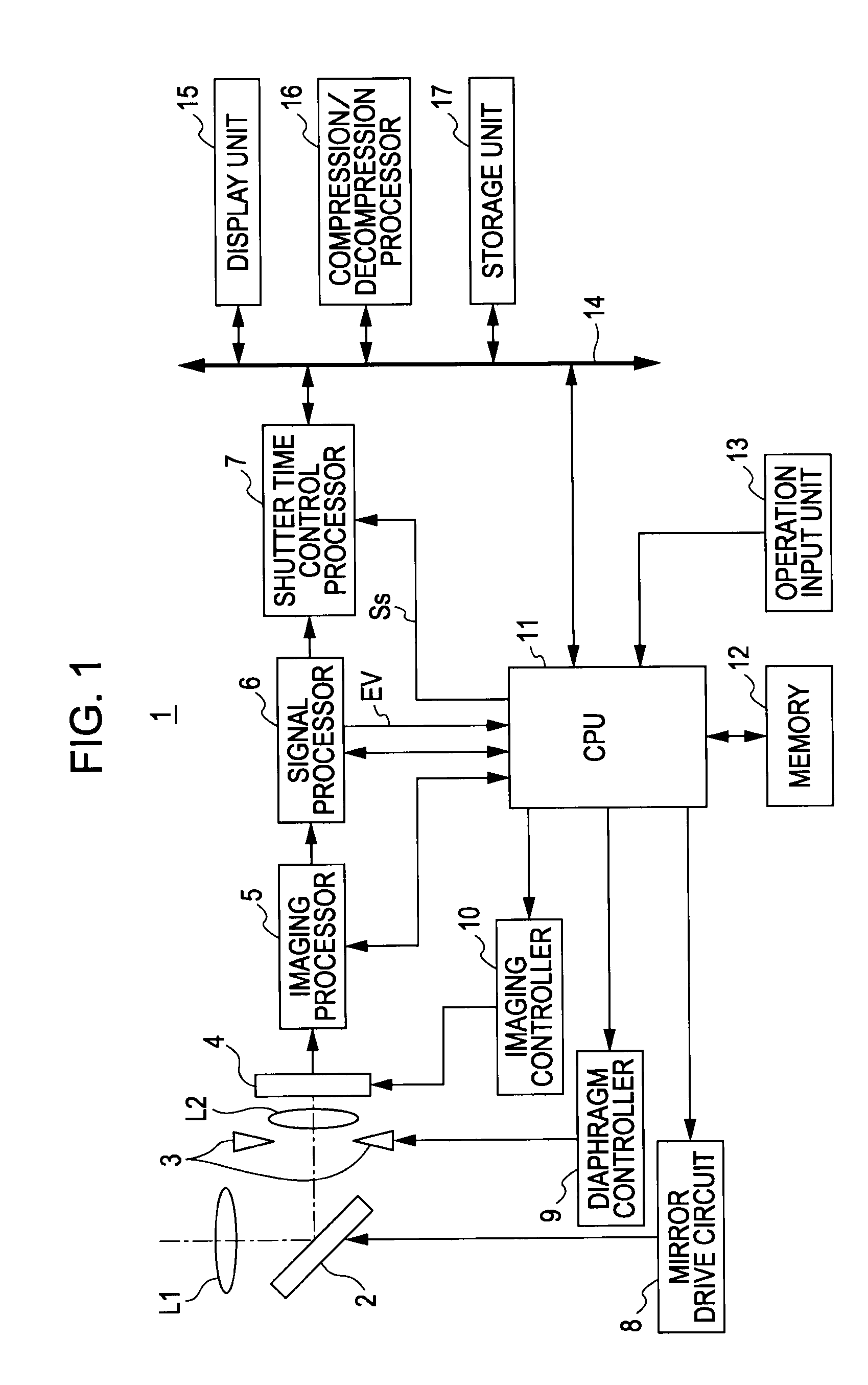
[0047]FIG. 1 is a block diagram illustrating the internal configuration of an imaging apparatus 1 in accordance with an embodiment of the present invention. The imaging apparatus 1 herein is configured as a video camera apparatus able to record video footage.

[0048]First, the imaging apparatus 1 is provided with imaging optics that include a lens L1, a deformable mirror apparatus 2, a lens L2, and a diaphragm 3.

[0049]The lens L1 and the lens L2 schematically represent lens groups in the imaging optics provided in order to resolve subject light (i.e., an image) onto the imaging elements 4 to be hereinafter described. The lens L1 schematically represents a lens group used to lead subject light to the deformable mirror apparatus 2, while the lens L2 schematically represents a lens group used to lead subject light reflected off the mirror surface of the deformable mirror apparatus 2 to the imaging elements 4. It should be appreciated that,...

second embodiment

[0208]A second embodiment will now be described. In the second embodiment, the frame periods are set to durations shorter than that of typical frame periods. In addition, the image reading period for the frame for recording footage and the image reading period for the frame for in-focus point search are differentiated by frame period.

[0209]FIGS. 15A and 15B are diagrams for explaining the concept of frame differentiation like that of the second embodiment. FIG. 15A illustrates the allocation of individual image reading readings, while FIG. 15B illustrates exemplary waveforms of the mirror drive signal.

[0210]As shown in FIG. 15A, the frame period in the second embodiment is set to a shorter duration than the frame period of the first embodiment (wherein the frame period is equal to the inverse of a frame frequency of 30 Hz). More specifically, the frame period in the present case corresponds to a frame frequency of 120 Hz. Furthermore, the image reading periods are allocated such tha...


PUM


Abstract

A focus control apparatus conducts a focus control with respect to an imaging apparatus configured to vary the focal point using a deformable mirror. An imaging unit first obtains image data via imaging elements and imaging optics provided in the imaging apparatus. A controller controls the driving of the deformable mirror such that, during a first image reading period wherein the reading of an image signal is periodically executed by means of the imaging elements, a focus drive state is achieved whereby an in-focus point that has been found in advance is set as the current focal point. During a second image reading period different from the first image reading period, the deformable mirror is controlled so as to achieve a focus drive state for in-focus point search.

Description

CROSS REFERENCES TO RELATED APPLICATIONS[0001]The present invention contains subject matter related to Japanese Patent Application JP 2007-304631 filed in the Japanese Patent Office on Nov. 26, 2007, the entire contents of which are incorporated herein by reference.BACKGROUND OF THE INVENTION[0002]1. Field of the Invention[0003]The present invention relates to a focus control apparatus and method for conducting a focus control with respect to an imaging apparatus configured to vary the focal length using a deformable mirror whose cross-sectional shape is deformable to convex or concave curvature.[0004]2. Description of the Related Art[0005]In the related art, video camera devices that record video footage typically conduct autofocus by searching for an in-focus point using a hill climbing technique. When a hill climbing technique is implemented in this way as the technique for searching for an in-focus point, the focal point is shifted to search for an in-focus point even while reco...

Claims


Application Information

Patent Timeline
Patent Type & Authority Applications(United States)
IPC IPC(8): H04N5/232G03B13/32G02B7/28G02B7/36G03B13/36H04N5/335H04N5/341H04N5/345
CPCG02B7/08G02B7/36G02B26/0825H04N5/243H04N5/2254H04N5/23212H04N5/23232G03B13/36H04N23/673H04N23/951H04N23/76
Inventor HIRAI, JUNAOKI, SUNAO
Owner SONY CORP
Why Eureka
Try Eureka