Method and apparatus for controlling recording laser power

a technology of laser power and recording laser, applied in the field of method and apparatus for controlling recording laser power, can solve the problems of unstable pit formation, unstable test recording and reproduction, and complex strategy (the waveform of recording laser beam) to achieve the effect of efficiently and accurately deciding the optimum value of recording laser power

Inactive Publication Date: 2005-07-28
JVC KENWOOD CORP A CORP OF JAPAN
View PDF9 Cites 13 Cited by
  • Summary
  • Abstract
  • Description
  • Claims
  • Application Information

AI Technical Summary

Benefits of technology

[0017] It is a first object of this invention to provide a method of controlling a recording laser power which includes a step of efficiently and accurately deciding an optimum value of the recording laser power.
[0018] It is a second object of this invention to provide an apparatus for controlling a recording laser power which includes a section for efficiently and accurately deciding an optimum value of the recording laser power.
[0019] It is a third object of this invention to provide a method of controlling a recording laser power which includes a step of guaranteeing that an LPP address signal can be correctly reproduced from a disc-shaped recording medium.
[0035] This invention provides advantages as follows. In this invention, during a time interval corresponding to a previously-recorded address signal on a disc-shaped recording medium, a test signal is recorded on the disc-shaped recording medium at a lowest recording laser power level. Therefore, the recording of the test signal is prevented from causing a disturbance in the reproduction of the previously-recorded address signal from the disc-shaped recording medium. Accordingly, even in the case where the disc-shaped recording medium undergoes test recording while being driven and scanned at a high constant linear velocity, the previously-recorded address signal can be utilized to the full after the test recording. Thus, even when an information signal is recorded on the disc-shaped recording medium by another drive apparatus, the recording of the information signal is prevented from halting. Therefore, it is possible to accurately implement the recording of the information signal on the disc-shaped recording medium.
[0036] In this invention, during a stepwise change of the recording laser power from a reference level to a highest level in test recording, the recording power of an applied laser beam is set to a prescribed level equal or close to the reference level for each of spaced time intervals corresponding to portions of a disc-shaped recording medium on which address signals are previously recorded respectively. Therefore, the recording of test signals on the disc-shaped recording medium prevents the occurrence of a reduction in an aperture ratio (AR) with respect to the previously-recorded address signals. Thus, even after the recording of the test signals, the previously-recorded address signals can be correctly reproduced from the disc-shaped recording medium.
[0037] In this invention, during a stepwise change of the recording laser power from a lowest level to a highest level in test recording, the recording power of an applied laser beam is set to a prescribed level equal or close to a reference level for each of spaced time intervals corresponding to portions of a disc-shaped recording medium on which address signals are previously recorded respectively. Therefore, the recording of test signals on the disc-shaped recording medium prevents the occurrence of a reduction in an aperture ratio (AR) with respect to the previously-recorded address signals. Thus, after the recording of the test signals, it is easy to properly set a signal detection level with respect to the previously-recorded address signals. Accordingly, the previously-recorded address signals can be correctly reproduced from the disc-shaped recording medium. In addition, it is possible to prevent a reproduced RF signal from being erroneously concluded to be absent.

Problems solved by technology

The great spontaneous vibration of the DVD-R causes the formation of pits therein to be unstable.
The unstable formation of pits means the unstable test recording and reproduction.
Especially, in the case of high-speed drive of the optical disc, the strategy (the recording laser beam waveform) is complicated and the margin for jitter is small so that a wide area is used for test recording and reproduction.
In this case, a required rotational speed of the optical disc is excessively high when an innermost portion of the optical disc is scanned by a laser beam.
Accordingly, it is undesirable to implement test recording and reproduction using an inner test area of the optical disc.
Generally, it is difficult to equalize the recording characteristics of the inner and outer test areas of an optical disc such as a DVD-R.
In the case where a resin layer of a polycarbonate substrate for a DVD-R is formed by injection molding from an inner side gate, it is difficult to make uniform the birefringence characteristics throughout a disc surface.
The outer test area of a DVD-R tends to scratch and be given fingerprints.
Thus, it is difficult to obtain exactly equal results of test recording and reproduction using the inner test area of a DVD-R and test recording and reproduction using the outer test area thereof.
It is difficult to correctly reproduce the LPP address signal from a disc in such a condition since land pre-pits (LPP) are hardly discriminated from recording marks.
In this case, there occurs the problem that the LPP address signal can not be correctly reproduced from the disc.

Method used


Image

  • Method and apparatus for controlling recording laser power
  • Method and apparatus for controlling recording laser power
  • Method and apparatus for controlling recording laser power

Examples


first embodiment

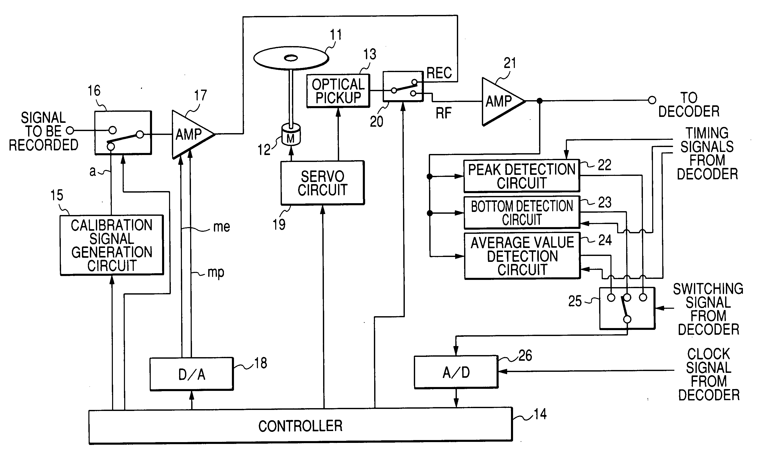
[0063]FIG. 3 shows a drive apparatus for an optical disc 11 according to a first embodiment of this invention. The drive apparatus in FIG. 3 includes an apparatus for controlling a recording laser power in this invention. The drive apparatus in FIG. 3 implements a method of controlling a recording laser power in this invention. Typical examples of the optical disc 11 are a DVD-R (a digital versatile disc recordable) and a DVD-RW (a digital versatile disc rewritable).

[0064] The drive apparatus in FIG. 3 operates in a mode selected from different modes including a test recording mode, a test reproducing mode, a normal recording mode, and a normal reproducing mode. As shown in FIG. 3, the drive apparatus includes a spindle motor 12 and an optical pickup 13. In operation of the drive apparatus, the spindle motor 12 rotates the optical disc 11 while the optical pickup 13 applies a laser beam to the optical disc 11. The rotation of the output shaft of the spindle motor 12, that is, the r...

second embodiment

[0136] A second embodiment of this invention is similar to the first embodiment thereof except for design changes mentioned hereafter. In the second embodiment of this invention, the controller 14 (see FIG. 3) operates to change the recording power of the laser beam in a profile different from that in FIG. 8 during every test recording procedure.

[0137]FIG. 9 shows the recording laser power change profile in the second embodiment of this invention. With reference to FIG. 9, the recording laser power change profile is divided into a first part and a second part which follows the first part in time domain. Accordingly, one test recording procedure is divided into a first part and a second part. One of the twenty-four intermediate levels of the recording power of the laser beam between the lower limit level PL and the upper limit level PH is equal or close to the expected optimum recording power PB, and is referred to as the specified level or the reference level.

[0138] During the fir...

third embodiment

[0143] A third embodiment of this invention is similar to the first embodiment thereof except for design changes mentioned hereafter. In the third embodiment of this invention, the controller 14 (see FIG. 3) operates to change the recording power of the laser beam in a profile different from that in FIG. 8 during every test recording procedure.

[0144]FIG. 10 shows the recording laser power change profile in the third embodiment of this invention. With reference to FIG. 10, one of the twenty-four intermediate levels of the recording power of the laser beam between the lower limit level PL and the upper limit level PH is equal or close to the expected optimum recording power PB, and is referred to as the specified level or the reference level.

[0145] During one test recording procedure, a test signal “a” in a 1-sync-frame-corresponding quantity is recorded on the inner PCA 33, the outer PCA 38, or one of the data-area test zones r1 and r2 twenty-six times while the recording power of ...


PUM

PropertyMeasurementUnit
constant-linear-velocityaaaaaaaaaa
linear velocityaaaaaaaaaa
recording poweraaaaaaaaaa

Abstract

Test signals are sequentially generated. A laser beam inclusive of the generated test signals is applied to a preset test recording area in a disc-shaped recording medium to record the generated test signals thereon. A recording power of the applied laser beam is changed stepwise from a lowest level to a highest level through different intermediate levels. The lowest level, the highest level, and the intermediate levels the recording power of the applied laser beam takes are assigned to the test signals respectively. The recorded test signals are reproduced from the preset test recording area in the disc-shaped recording medium. An optimum value of a laser-beam recording power is decided on the basis of the reproduced test signals and at least one of the lowest level, the highest level, and the intermediate levels.

Description

BACKGROUND OF THE INVENTION [0001] 1. Field of the Invention [0002] This invention generally relates to a method and an apparatus for controlling a recording laser power. This invention specifically relates to a method and an apparatus for controlling the recording power of a laser beam applied to a disc-shaped recording medium or an optical disc such as a DVD-R, a DVD-RW, a DVD+RW, or a DVR-Blue. [0003] 2. Description of the Related Art [0004] Optical discs contain a CD (compact disc) and a DVD (digital versatile disc). A CD-RW, a DVD-R, a DVD-RW, a DVD+RW, and a DVR-Blue are disc-shaped recording mediums of an organic dye type or a phase change type which each have a continuous recording track and address information intermittently formed along a side of the track at intervals corresponding to a prescribed recording unit. [0005] There is a drive apparatus for optically recording and reproducing an information signal on and from such a disc-shaped recording medium while applying a ...

Claims


Application Information

Patent Timeline
Patent Type & Authority Applications(United States)
IPC IPC(8): G11B5/09G11B7/00G11B7/0045G11B7/005G11B7/125G11B7/1267
CPCG11B7/1267G11B7/0053
Inventor UEKI, YASUHIRO
Owner JVC KENWOOD CORP A CORP OF JAPAN
Why Eureka
Try Eureka