Moisture meter with impedance and relative humidity measurements

a technology of impedance and relative humidity, applied in the field of moisture meters, can solve problems such as floor failur

Inactive Publication Date: 2001-08-30
RYNHART RES LTD
View PDF0 Cites 18 Cited by
  • Summary
  • Abstract
  • Description
  • Claims
  • Application Information

AI Technical Summary

Problems solved by technology

Excess moisture could lead to problems of condensation causing swelling and peeling of the...

Method used


Image

  • Moisture meter with impedance and relative humidity measurements
  • Moisture meter with impedance and relative humidity measurements
  • Moisture meter with impedance and relative humidity measurements

Examples


Embodiment Construction

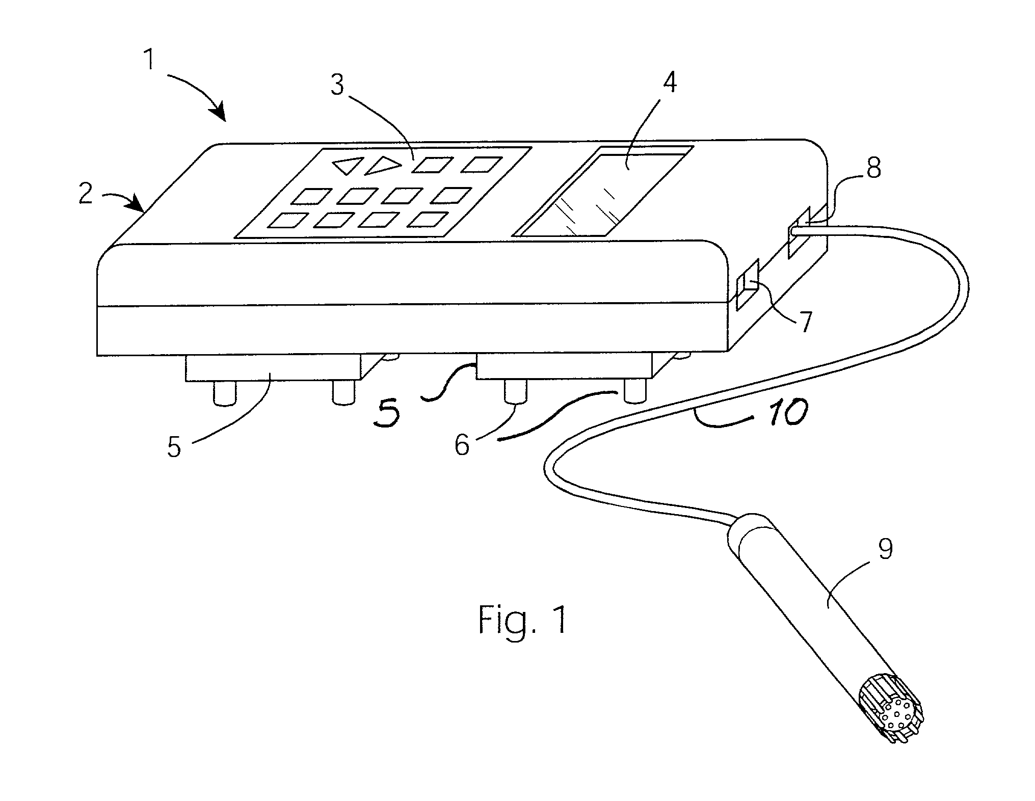
[0051] Referring to FIG. 1, a moisture meter 1 of the invention is shown. The meter 1 comprises a housing 2 supporting sensor and data processing circuits, a keypad 3, and a dot matrix display 4. The housing 2 also supports two electrodes 5 for impedance measurement and four spring-loaded gold-plated contacts 6 extending from each electrode 5. The contacts 6 each have a 4 mm plunger and a spring resistance of 300 grams. The meter 1 also comprises an RS232 socket 7 for connection to a computer, and a socket 8 connected by a lead 10 to a relative humidity probe 9. An on / off switch may also be connected in the top of the meter, alongside the socket 7.

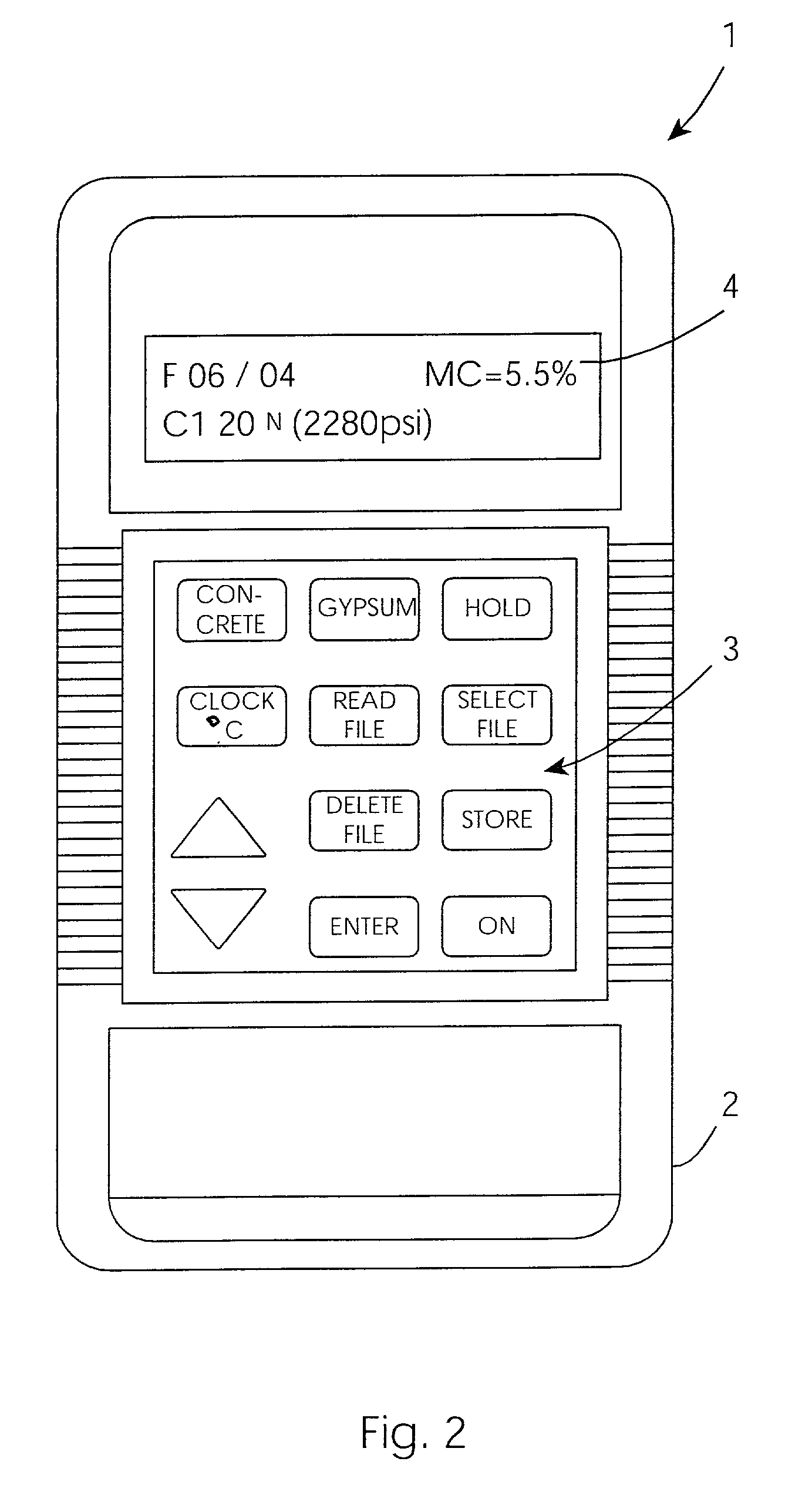
[0052] The keypad 3 is shown more clearly in FIG. 2. It comprises dedicated function keys for concrete and for gypsum selection. For data file management, there are Read File, Select File, Delete File, Store, and Enter keys. A further key (Clock / .degree. C.) is used for adjustment and display of temperature and time data. There are als...


PUM


Abstract

A moisture meter (1) has a hand-held casing (2) with a digital microcontroller (50), LCD display (4), and a keypad (3). Spring-loaded contacts (6) contact material and allow capacitive impedance measurement via electrodes (5) and drive/pickup circuits (20). Also, a relative humidity probe (9) provides an input so that the processor generates both moisture contact near-surface measurements and also relative humidity measurements. This allows optimum analysis of material.

Description

[0001] 1. Field of the Invention[0002] The invention relates to a moisture meter, particularly for masonry materials such as concrete or gypsum structures.[0003] 2. Prior Art Discussion[0004] Concrete floors must be allowed to dry to an adequate level before they are covered with sheet, tiles, coatings or timber flooring. Excess moisture could lead to problems of condensation causing swelling and peeling of the covering and condensation, blistering or deterioration of adhesives leading to flooring failure.[0005] No period can be specified for the drying of concrete as this is affected by temperature and humidity within the building. For this reason the concrete slab should be regularly checked to monitor the drying process.[0006] Japanese Patent Specification No. JP11006797 describes measurement of moisture content of cast concrete. The system uses infra-red radiation at a multiplicity of locations in a grid.[0007] The invention is directed towards providing a moisture meter which a...

Claims


Application Information

Patent Timeline
IPC IPC(8): G01N27/22
CPCG01N27/223
Inventor RYNHART, ALANFALLON, JOHNMCILROY, JAMES
Owner RYNHART RES LTD
Why Eureka
Try Eureka