Shock absorber for cycle and methodology incorporating the same

a shock absorber and cycle technology, applied in the direction of frictional roller transmission, steering device, cycle equipment, etc., can solve the problems of rider discomfort, rider fatigue in the knee joints, and inability to innovate very well, and achieve the effect of preventing the impact of operation

Inactive Publication Date: 2001-10-04
EZRYD
View PDF0 Cites 4 Cited by
  • Summary
  • Abstract
  • Description
  • Claims
  • Application Information

AI Technical Summary

Benefits of technology

[0009] It is an object of the present invention to provide a new and improved shock absorber for use with wheeled vehicles, such as bicycles, tricycles, motorcycles and the like, to cushion against impacts occurring during operation.
[0012] Still a further object of the present invention to provide such a shock absorber which is relatively lightweight so that it has minimal effect on the overall weight of the cycle.
[0013] Yet another object of the present invention is to provide a new and improved method for cushioning impact during operation of a cycle.
[0016] The biasing assembly is coupled between the first and second tubular members so that movement of the second tubular member in a first direction along the longitudinal axis away from the initial position is resisted by the biasing assembly. The biasing assembly is further operative in response to such movement in the first direction to exert a restorative force to urge the second tubular member in a second direction along a longitudinal axis of the first tubular member and toward the initial position, thereby to cushion the seat assembly and the drive assembly relative to impacts occurring during operation of the cycle.
[0020] The present invention also contemplates a method for cushioning impact during operation of a cycle which is adapted to travel in an upright position along a support surface. This methodology broadly comprises a first of rigidly interconnecting the cycle's seat assembly and the drive assembly's foot supports for reciprocal, common movement in upward and downward directions relative to the frame. The methodology also includes a second step of exerting a restorative force on the seat assembly and the foot supports to urge them upwardly toward an initial position relative to the frame in response to a displacement of the seat assembly and foot supports in a downward direction away from this initial position.

Problems solved by technology

This invention was not very successful because the pedals did not rotate, but rather followed circular arcs which caused rider fatigue in the knee joints.
Such surface discontinuities, over prolonged period of riding time, can result in discomfort to the rider and increased fatigue as the rider attempts to reposition himself / herself on the bicycle in anticipation of upcoming obstacles.

Method used


Image

  • Shock absorber for cycle and methodology incorporating the same
  • Shock absorber for cycle and methodology incorporating the same
  • Shock absorber for cycle and methodology incorporating the same

Examples


Embodiment Construction

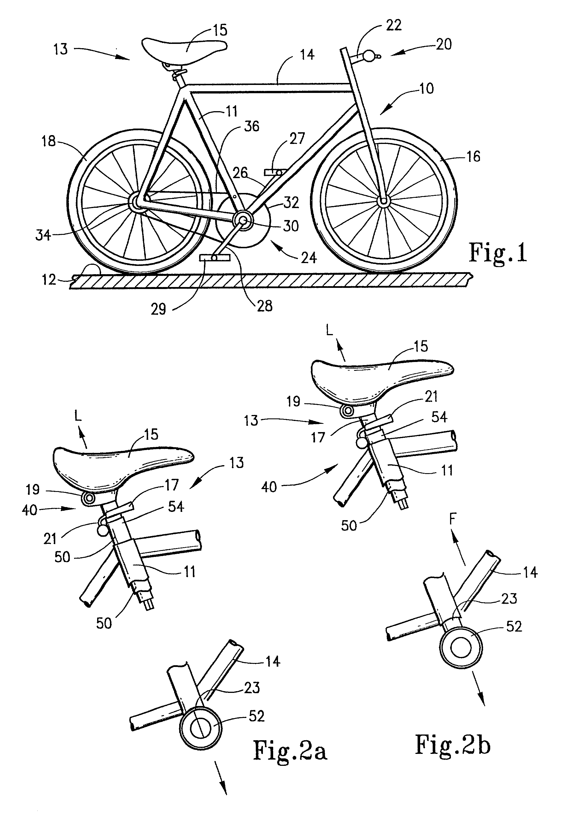
[0034] The present invention generally concerns shock absorbers, and is more specifically directed to shock absorbers for use with cycles to cushion against impacts occurring during operation. While the present invention is described herein with reference to a bicycle in the form of a mountain bike, it should be appreciated that the principal features of the shock absorber can also be implemented into other types of wheeled vehicles, such as tricycles, racing bikes or even some motorized vehicles. The shock absorber is especially adapted for use in the seated region of the cycle to cushion the seat assembly and the drive assembly relative to impacts resulting from bumps, pot holes, rocks or other discontinuities in the riding surface.

[0035] Accordingly, and as generally introduced in FIG. 1, the shock absorber is adapted for use with a cycle 10 adapted to travel in an upright position along a support surface 12. Cycle 10 may be a conventional mountain bike so that it includes a rigi...


PUM


Abstract

A shock absorber for use with a cycle comprises elongated first and second tubular members and a biasing assembly. The first tubular member is associated with the cycle's frame and has a longitudinal axis. The second tubular member has a lower end portion adapted for connection to foot supports and an opposite upper end portion for connection to the cycle's seat assembly such that the foot supports and the seat assembly are interconnected for common movement. The second tubular member is slidably disposed with respect to the first tubular member for movement along the longitudinal axis away from an initial position as determined by a pre-impact condition. The biasing assembly is coupled between the tubular members so that movement of the second tubular member in a first direction away from the initial position is resisted by the biasing assembly, which responds with a restorative force to urge the second tubular member in a second direction toward the initial position thereby cushioning the seat and drive assemblies relative to impacts during operation. A methodology for cushioning impacts during operation is also disclosed.

Description

[0001] This is a division of application Ser. No. 09 / 173,057, filed Oct. 15, 1998, now U.S. Pat. No. ______.[0002] The present invention is broadly directed to shock absorbers for use with wheeled vehicles to cushion against impacts during use. The present invention is more particularly directed to shock absorbers disposed in the seated region of a wheeled vehicle, such as a bicycle and the like, to cushion the seat assembly and the drive assembly relative to impacts occurring during operation by imparting common movement thereto. A cycle incorporating such a shock absorber and a methodology for cushioning impact during operation of a cycle are also provided.[0003] While the origin of the bicycle dates as far back as the mid-17th century, when wheeled vehicles were moved by the action of pushing on the ground with one's feet, the real technical innovation in this domain came in the early 19th century with the invention of swinging pedal cranks for two wheeled vehicles. At that time,...

Claims


Application Information

Patent Timeline
Patent Type & Authority Applications(United States)
IPC IPC(8): B62J1/06B62K19/34
CPCB62J1/06B62K19/34
Inventor SMITH, JERRY R.
Owner EZRYD
Why Eureka
Try Eureka