Image display apparatus and personal computer for displaying personal computer signals and broadcast signals

a technology for displaying apparatus and personal computers, applied in the direction of television systems, instruments, color signal processing circuits, etc., can solve the problems of vertical resolution degradation, line and even-field scan lines will substantially overlap, and the vertical resolution of this image will declin

Inactive Publication Date: 2001-10-11
HITACHI LTD +1
View PDF0 Cites 16 Cited by
  • Summary
  • Abstract
  • Description
  • Claims
  • Application Information

AI Technical Summary

Problems solved by technology

However, an incompatibility problem arises in that display signals for NTSC system television sets use a 15.75 kHz horizontal deflection frequency, for example, while display signals for personal computers generally use a 31.5 kHz or more horizontal deflection frequency, for example.
Despite the ability to display the NTSC signal, when an interlace scanning signals such as an NTSC signal is converted to a double-speed signal, it was found that a vertical resolution of this image declines.
Still further, in a case where a still image is displayed, vertical resolution degradation becomes visible.
A problem, however, exists in that as a result of duplication, various odd-field scan lines and various even-field scan lines are now vertically positioned at positions within the odd-field display frame 70 and even-field display frame 80, respectively, such that odd-field scan lines and even-field scan lines will substantially overlap each other during an interlacing operation.
Thus resolution degradation is experienced in that, instead of seeing the expected exemplary (alternating) black-white-black-white .
However, this time to avoid the overlapping and resultant resolution degradation problem, a further vertical shifting operation is applied to each duplicate scan line, such that each original scan line and its duplicate scan line are caused to overlap one another.
However, such technique suffers from at least two deficiencies.
More particularly, first, in a case where a double-speed signal converted in advance is inputted from outside an apparatus (e.g., via an external input terminal), the arrangement disclosed in such publication cannot distinguish which raster scanning line must be vertically shifted in order to avoid the resolution degradation problem in an overlaying scan , i.e., all incoming scan lines appear the same to the apparatus as there is no information to distinguish shift scan lines from non-shift scan lines.
Therefore, in a case where a double-speed signal converted in advance is inputted into the apparatus of such technique, necessary and proper vertical shifting cannot be determined or performed, and therefore vertical resolution of a corresponding image becomes degraded.
A second deficiency, while the above technique may work for a situation when one scanning speed is used consistently across an entire screen (FIG. 9), such background approach is disadvantageous when scanning speed and thus selective vertical shifting must be changed from area-to-area within a screen (i.e., intrascreen), for example, in a picture-in-picture operational mode such as illustrated in FIG. 8 which displays a PC display signal in an image b screen portion and an NTSC signal in an image a screen portion.
More particularly, when an overlaying scan (including vertical shifting) is executed for an entire screen, for example, in a case where a signal of the image that is indicated in FIG. 8 is attempted, the vertical resolution of a PC image (image b) declines as selected scanning lines thereof are vertically shifted causing resolution degradation and / or scrambling of the display lines.
To the contrary, when an overlaying scan (including vertical shifting) is not executed, the vertical resolution of a double-speed NTSC image (image a) declines as the resolution degradation problem discussed above occurs.

Method used


Image

  • Image display apparatus and personal computer for displaying personal computer signals and broadcast signals
  • Image display apparatus and personal computer for displaying personal computer signals and broadcast signals
  • Image display apparatus and personal computer for displaying personal computer signals and broadcast signals

Examples


Embodiment Construction

[0030] Before beginning a detailed description of the subject invention, mention of the following is in order. More particularly, when appropriate, like reference numerals and characters are used to designate identical, corresponding or similar components in differing figure drawings.

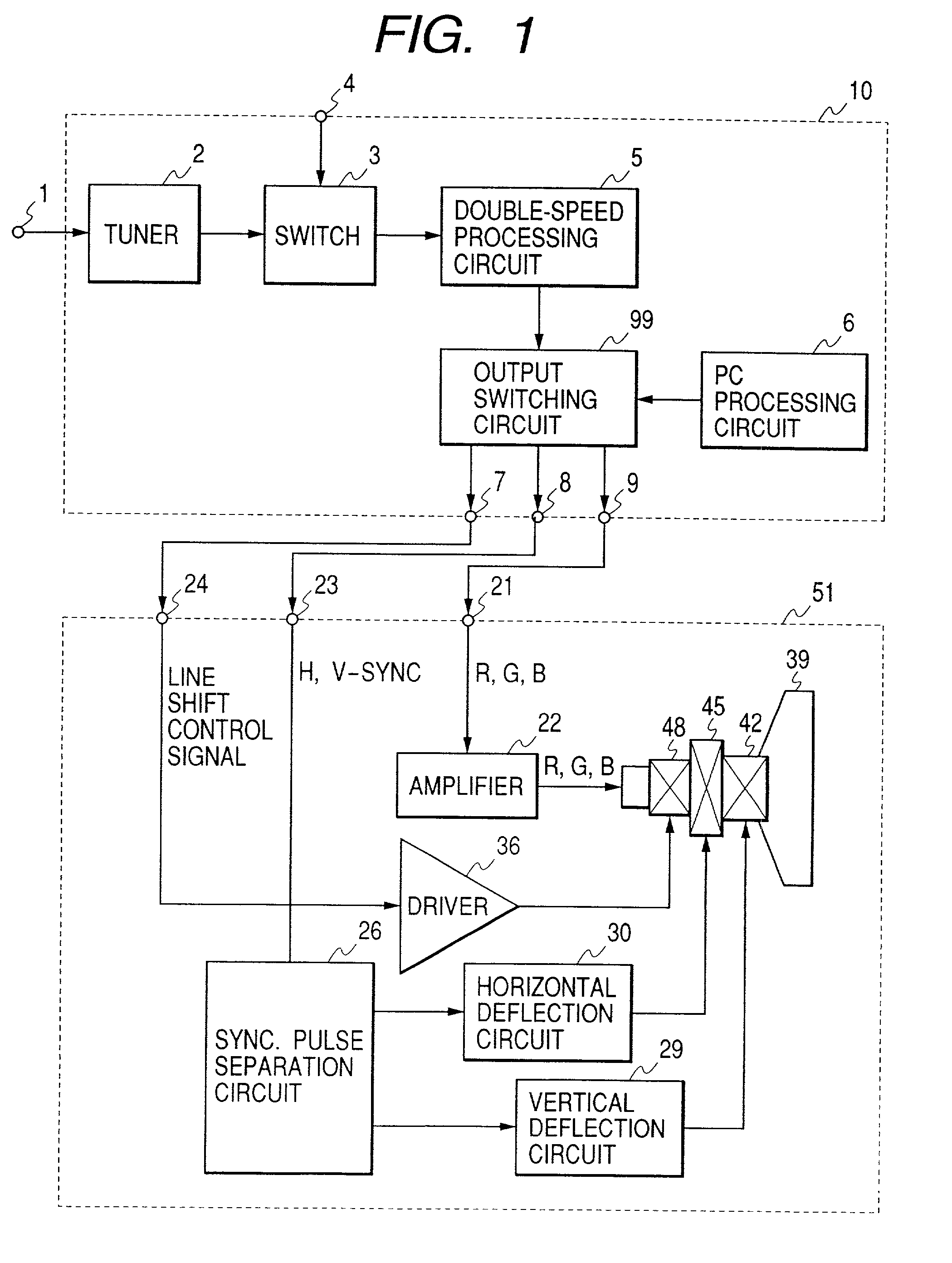
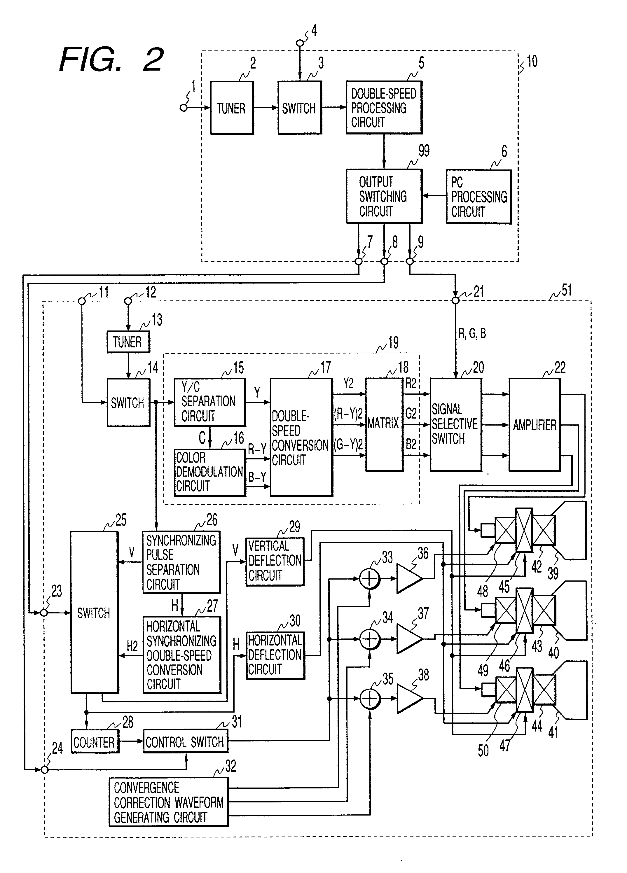
[0031] Hereinafter, description will be made of embodiments according to the present invention with reference to the drawings. More specifically, FIG. 1 is a block diagram showing a first embodiment of an image display system according to the present invention, i.e., as applied to a cathode ray tube (CRT) display device. More particularly, the FIG. 1 embodiment is composed of a device 10 including a display signal generator such as a personal computer, and a device 51 including a display unit. The device 10 preferably includes an antenna input terminal 1, a tuner 2, a switch 3, an external video input terminal 4, a double-speed processing circuit 5, a PC processing circuit 6, an output switching circuit...


PUM


Abstract

When a video signal is double-speed processed by the first device, a slight vertical deflection process is performed for redundant similar scan lines by the second device, and any slight deflection in the second device is controlled by the first device to thereby enable setting so as to always display images with excellent resolution. More particularly, a discrimination signal is generated by the first device to designate interlaced scanning and flag a need for vertical scan-line deflection, and such discrimination signal is provided to the second device such that the second device can always appropriately determine the need for vertical scan-line deflection. Through monitoring for the discrimination signal, an image display apparatus is capable of preventing vertical resolution from being deteriorated when video signals possibly requiring vertical line-shifting are inputted from an external source. Further, an image display apparatus is capable of preventing the vertical resolution from being deteriorated when images of video signals having different systems are displayed within different areas on a same screen.

Description

[0001] 1. Field of the Invention[0002] The present invention relates to a preferred signal display system applicable to image display apparatuses, display devices or television sets for displaying a plurality of video signals having different scanning frequencies such as video signals of the NTSC system, output video signals from personal computers (hereinafter, alternatively referred to as PC signals) and the like. More particularly, the present invention further relates to a multimedia type personal computer capable of outputting both PC display signals (such as VGA signals) and interlace scanning signals (such as an NTSC signal) converted to double-speed (hereinafter, alternatively called "double-speed signal"), and also relates to an image display apparatus possibly connected thereto for displaying both the image of a PC display signal and a double-speed signal, i.e., capable of displaying such differing signals simultaneously as well as at differing times. Especially, the prese...

Claims


Application Information

Patent Timeline
Patent Type & Authority Applications(United States)
IPC IPC(8): G09G1/04H04N3/27H04N5/44H04N5/45H04N5/46H04N5/68H04N9/28H04N9/64
CPCG09G1/04G09G2310/0229H04N3/27H04N5/4401H04N5/68H04N9/641H04N21/4122H04N21/4143H04N21/440218H04N21/426
Inventor WATANABE, TOSHIMITSUTSUKAHARA, MASAHISAKABUTO, NOBUAKI
Owner HITACHI LTD
Why Eureka
Try Eureka