
Pipeline identification and positioning system

a positioning system and pipeline technology, applied in the direction of pipes, pipe laying and repair, instruments, etc., can solve the problems of insufficient features of most pipelines, inconvenient inspection of pipelines, and inability to locate defects, etc., and achieve the effect of accurate recording of changes

Inactive Publication Date: 2001-10-18
PAZ GERMAN N
View PDF0 Cites 67 Cited by
  • Summary
  • Abstract
  • Description
  • Claims
  • Application Information

AI Technical Summary

Benefits of technology

[0018] The Pipeline Identification And Positioning System ("PIPS") of the present invention comprises a permanent, passive, non-obtrusive, and systematic placement of markers that uniquely identify a pipeline or a specific location in a pipeline. As will be hereinafter described, PIPS assigns an identification code to locations selected by the pipeline operator that may be detected by inspection methods known in the art. As will be appreciated by those skilled in the art, PIPS enables the accurate recording of changes in pipe wall thickness via ultrasonic, radiographic, magnetic detection methods and the like.

Problems solved by technology

Unfortunately, most pipelines do not have enough features to help correlate a buried section of pipe to a visible benchmark above-ground.
Excavating a pipeline to locate a defect is a very expensive process.
Many factors contribute to costly errors in pipeline inspection with smart pigs.
Faulty correlation of distances jeopardizes the effectiveness of the inspection service and creates hazardous conditions for the public at large.
For instance, while smart pigs travel the buried pipeline, such pipelines do not necessarily follow the profile of the terrain above-ground.
As another example, pipeline operators may monitor operational parameters, but cannot micro-manage and control product speed, pressure, and other parameters required by smart pigs throughout the inspection run.
Electronic pipeline markers are inherently prone to suffer from interference by stray radio or electronic signals.
Excavations are costly and have to be scheduled in advance.
Similarly, while the Global Positioning System (GPS) helps to record accurate references above-ground, it fails to record both pig position and pipeline location at the same time.
Operators cannot routinely acquire understanding and knowledge of each such inspection methodology.
Furthermore, retraining of crews is often necessary for the prerequisite inspection to occur.
Moreover, typical inspection logistics dictate that magnets be shipped in sufficient numbers or, otherwise, the operator must leap-frog the limited available magnet units during the survey.
As will be appreciated by those conversant with the art, some geographic locations are not safe for placement of inspection equipment at night particularly during a protracted inspection run.
Another inherent infirmity of prior art pipeline inspections is that inspection companies assume little or no liability if the signals produced by these magnets are confused with other signals such as existing taps, patches or any metallic mass that resemble magnet signals.
Still another well known problem in the art is that missing magnets leave voids that jeopardize the integrity and accuracy of the inspection.
Electronic markers may not be detected by the smart pig due to: malfunction in the additional components, stray radio or electronic signals, deeper than expected pipeline, or misplacement of marker in a multiple corridor of pipelines.
Problems also arise when signals are recorded in the wrong places.
There is presently no method known in the art that distinguishes the units which fail from those that do not.
On several occasions in the field, unfortunately, this happens weeks or even months after the inspection report has been received wherein budgets have already been allocated for repairs of all pipeline defects.
If an error is discovered it usually means several defects are being excavated in the wrong areas.
Many pipelines, unfortunately, are excavated in urban areas with the consequent disruptions of neighborhoods.
Thus, there appears to be no available fail-safe and unobtrusive methodology for reliably and accurately identifying and positioning pipelines.

Method used


Image

  • Pipeline identification and positioning system
  • Pipeline identification and positioning system
  • Pipeline identification and positioning system

Examples


Embodiment Construction

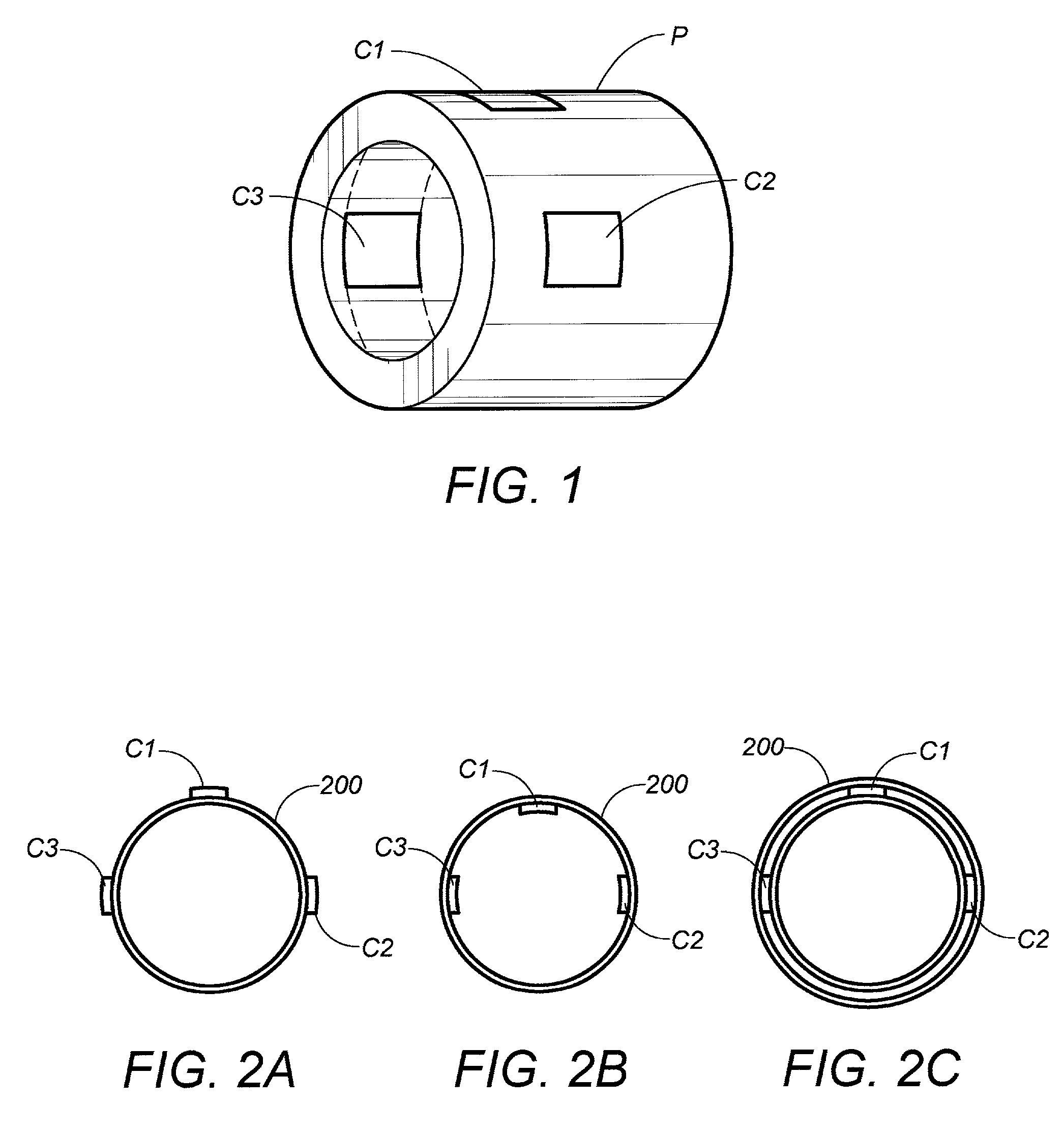
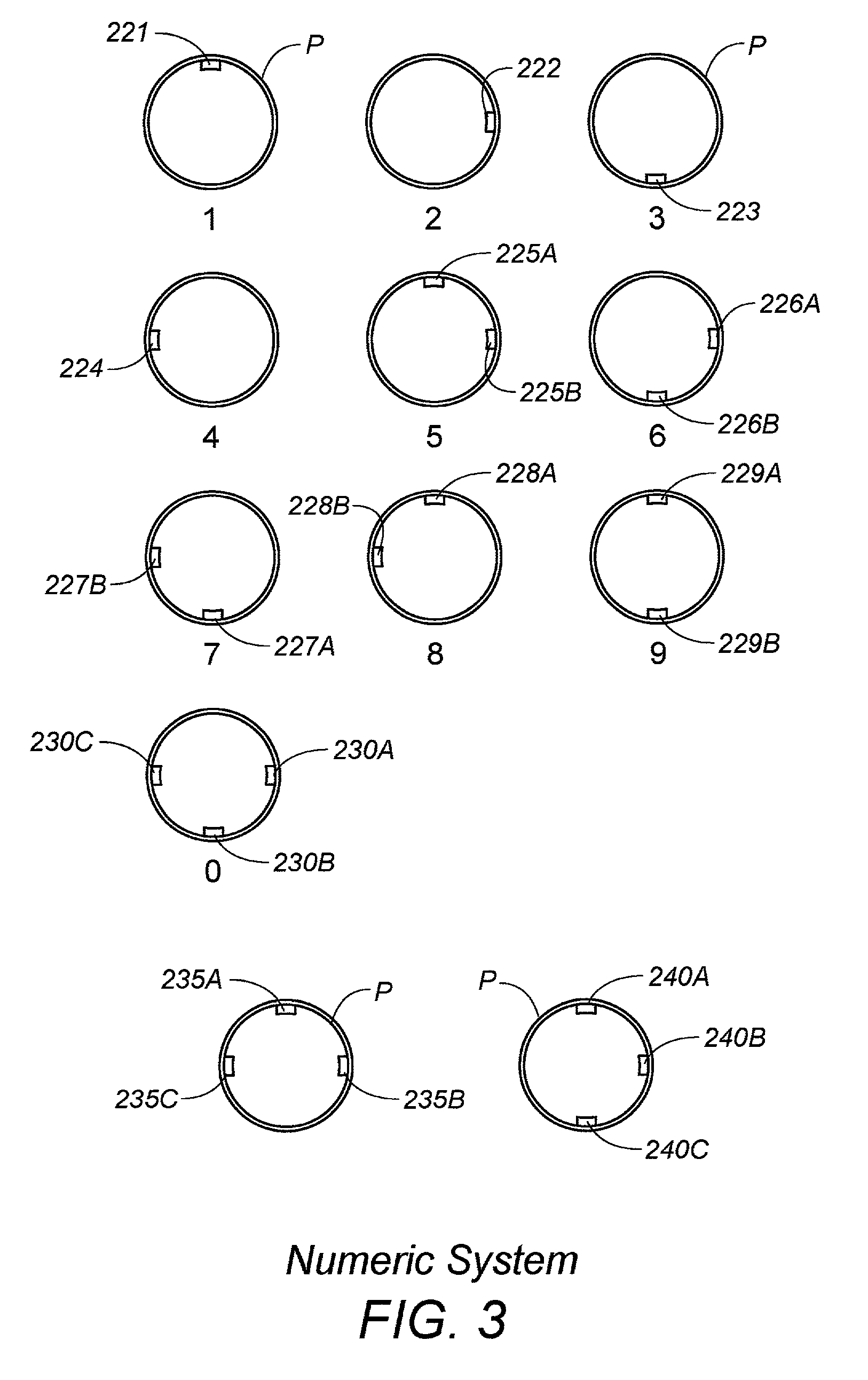
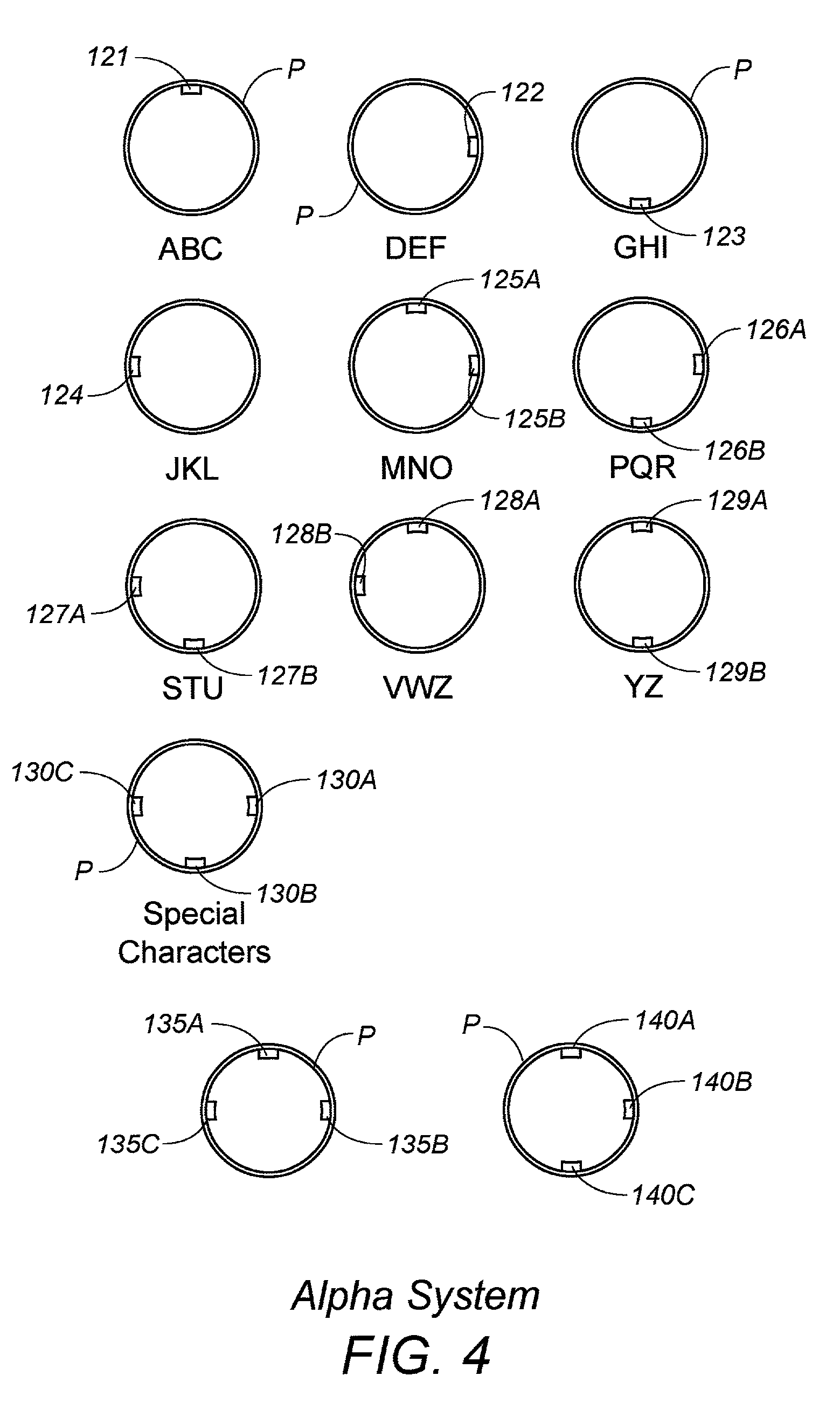
[0038] The pipeline identification and positioning system ("PIPS") of the present invention comprises a systematic application of a plurality of in situ markers that enable changes in local pipeline thickness to be identified and located. As will be hereinafter described in detail, the preferred embodiment of PIPS provides a code structure incorporated into this plurality of in situ markers that is "readable" by smart pigs or other comparable detection devices known in the art. It will be appreciated by those skilled in the art that such detection devices use a variety of technologies and concomitant resolutions for inspecting pipelines.

[0039] It will be understood that markers taught by the preferred embodiment of the present invention are designed for detection by the lowest resolution available in the art. Such a characteristic, of course, assures universal detection of pipeline irregularities or the like, independent of the particular detection device or technology used. It is a...


PUM


Abstract

A system for identifying and positioning pipelines that accurately and unequivocally marks a section of pipeline and tubular goods located anywhere for subsequent identification. The pipeline positioning system comprises a permanent, passive, non-obtrusive, and systematic placement of marker coupons upon pipe diameters for uniquely identifying a pipeline or specific location therein. Identification and location codes incorporated into the markers may be readily detected by inspection methods known in the art. Codes may be applied to new tubes or pipelines during manufacturing, during pipeline laying operations, or during maintenance being rendered by the pipeline owner or operator.

Description

RELATED APPLICATIONS[0001] This application claims priority based upon provisional application Ser. No. 60 / 183,290 filed Feb. 17, 2000.BACKGROUND OF THE INVENTION[0002] Gas and petroleum products are transported on a worldwide basis by routinely passing through systems of pipelines constructed of different sizes and lengths. It is well known in the art that a substantial investment of time and money is associated with establishing and maintaining a pipeline system of such global extent. It is also well known in the art that the implicated plurality of pipelines is normally protected by certain features that are intended to prevent damage and corrosion. While most pipeline systems are designed to operate continuously for several years without interruption, a plethora of factors actually determine the life expectancy thereof.[0003] As is well known in the art, Smart Pigs are electronic instruments designed to inspect pipelines internally while physically traveling with a fluid product...

Claims


Application Information

Patent Timeline
IPC IPC(8): F16L1/11F16L55/48
CPCF16L1/11F16L55/48G01V15/00
Inventor PAZ, GERMAN N.
Owner PAZ GERMAN N
Features
  • Generate Ideas
  • Intellectual Property
  • Life Sciences
  • Materials
  • Tech Scout
  • Unparalleled Data Quality
  • Higher Quality Content
  • 60% Fewer Hallucinations
Learn More