Stator iron core of electric motor, manufacturing method thereof, electric motor, and compressor

a technology of electric motors and steel cores, which is applied in the direction of dynamo-electric machines, magnetic circuit shapes/forms/construction, supports/enclosements/casings, etc., can solve the problems of reducing the efficiency of electric motors, reducing the performance of magnetic materials, and difficulty in maintaining a sufficient stiffness

Inactive Publication Date: 2001-10-18
MITSUBISHI ELECTRIC CORP
View PDF0 Cites 42 Cited by
  • Summary
  • Abstract
  • Description
  • Claims
  • Application Information

AI Technical Summary

Problems solved by technology

Accordingly, the performance of the magnetic material is reduced, which causes problems that the efficiency of the electric motor is reduced, it becomes difficult to keep a sufficient stiffness, and further, vibration or noise may be generated during the driving of the electric motor.
This means the stator iron core tend to be influenced by the dimensional precision of the housing and the like, namely, a circularity of the outer circumference and the inner circumference of the stator iron core of the electric motor tends to become worse by the contact force at the time of shrink-fitting or press-fitting.
Further, when the circularity becomes worse, an air gap between the stator and the rotor becomes irregular at the time of driving the electric motor.
This may generate magnetic unbalance of the electric motor, and also causes a problem to generate noise or vibration.
Accordingly, the confronting surfaces 101b and 101c of the end portions are easily dislocated in the radius direction at the time of circularly forming the stator, which makes it difficult to keep the mechanical precision of the stator.
Therefore, when the stator is assembled in the electric motor, the magnetic performance of the magnetic material is decreased to cause problems that the efficiency of the electric motor becomes worse, the magnetic unbalance may be generated, and vibration or noise may be generated on driving the motor.
Even if the connection portion is made bendable by some means in the stator, the confronting surfaces 101b and 101c of the end portions are easily dislocated in the radius direction, which causes the same problem as above.
Even if the portions have an arc portion, the confronting surfaces 101b and 101c of the end portions are easily dislocated in the radius direction, which causes the same problem as above.

Method used


Image

  • Stator iron core of electric motor, manufacturing method thereof, electric motor, and compressor
  • Stator iron core of electric motor, manufacturing method thereof, electric motor, and compressor
  • Stator iron core of electric motor, manufacturing method thereof, electric motor, and compressor

Examples


embodiment 1

[0071] In the following, the first embodiment of the present invention will be explained by referring to the figures.

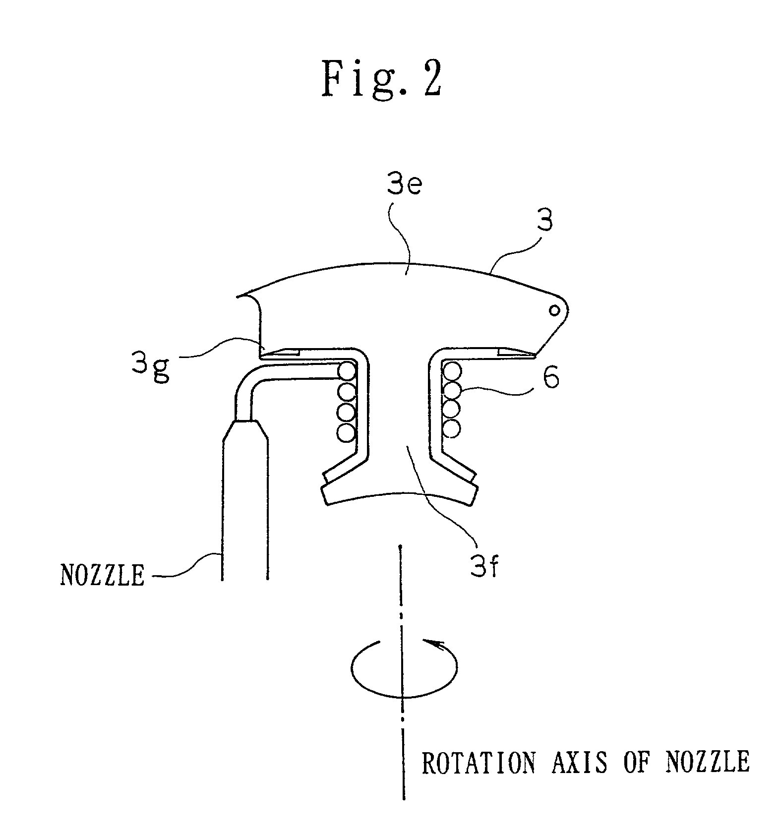
[0072] FIGS. 1 and 2 show the first embodiment. FIG. 1 is a plan view of a stator of an electric motor, and FIG. 2 is a plan view showing a part of the electric motor and explaining how to wind a coil wire of the stator of the electric motor.

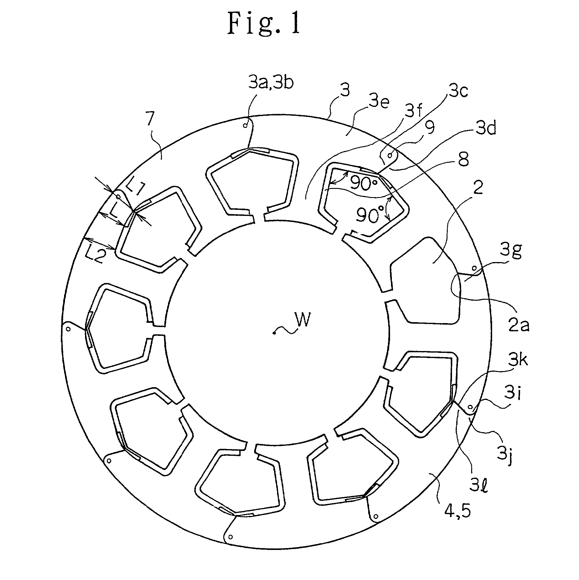
[0073] In FIG. 1, a reference numeral 1 shows a plate-shaped core segment (magnetic pole segment) made of magnetic material, and a reference numeral 9 shows a connection portion (also called as a joint portion) consisting of a concave portion 3a and a convex portion 3b provided to both surfaces of one end of the magnetic pole segment 3 as a connection means. 4 shows the first iron core member in which plural magnetic pole segments 3 are aligned via an end face 3c and an end face 3d of each segment.

[0074] A reference numeral 5 shows the second iron core member in which plural magnetic pole segments 3 are aligned, and the second iro...

embodiment 2

[0082] In the following, the second embodiment of the present invention will be explained referring to the figures.

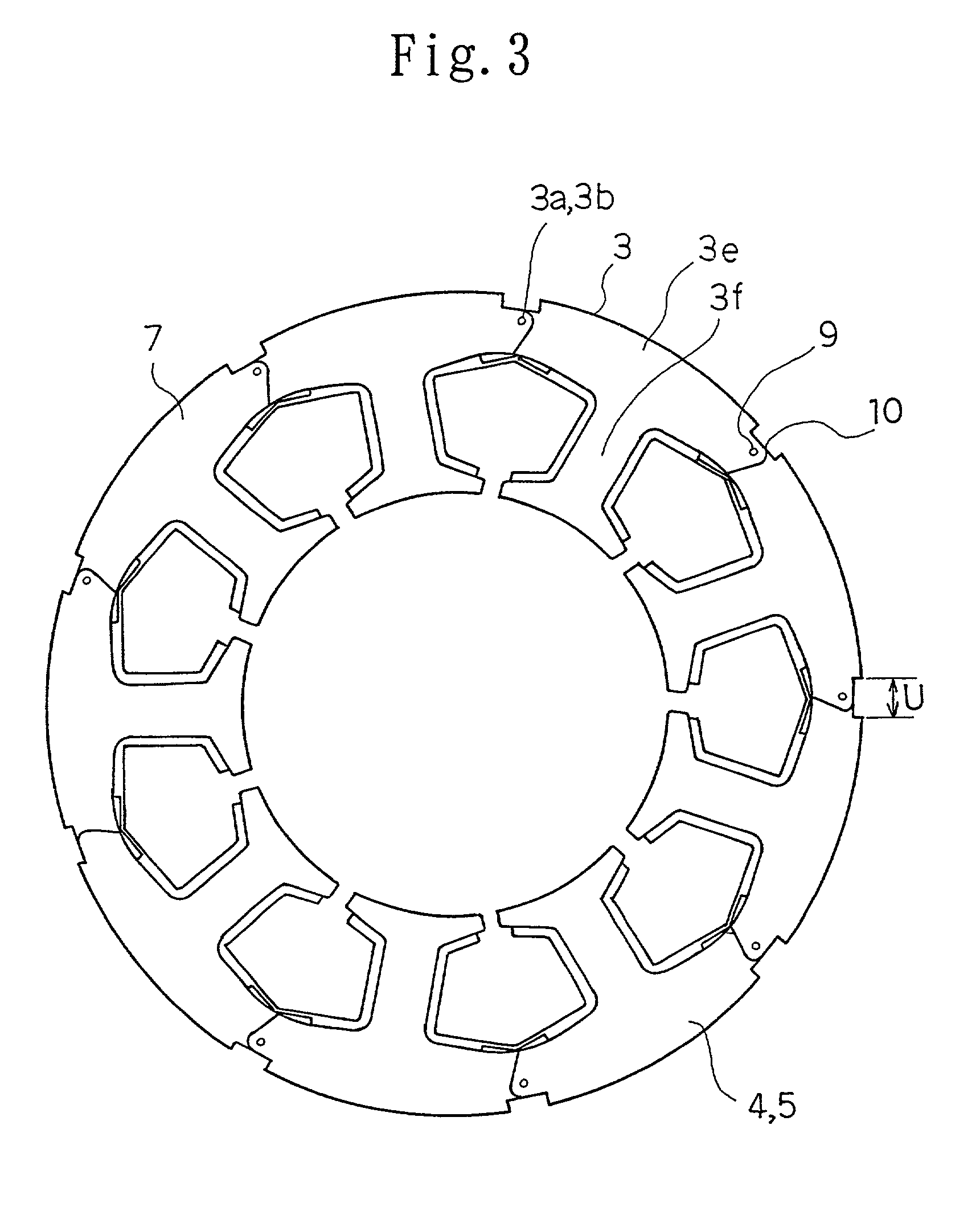
[0083] FIG. 3 shows a plan view of the stator of the electric motor according to the second embodiment. In FIG. 3, a reference numeral 3 shows a plate-shaped core segment (magnetic pole segment) made of the magnetic material. A reference numeral 9 shows a connection portion constituted by a concave portion 3a and a convex portion 3b provided to both surfaces of one end of the magnetic pole segment 3 as a connection means. 4 shows the first iron core member in which plural magnetic pole segments 3 are aligned via an end face 3c and an end face 3d of each segment.

[0084] A reference numeral 5 shows the second iron core member in which plural magnetic pole segments 3 are aligned, and the second iron core member and the first iron core member are stacked or laminated alternately. The concave portion 3a of a certain magnetic pole segment 3 is engaged with the convex portion 3...

embodiment 4

[0097] In the following, the fourth embodiment of the present invention will be explained referring to the figures.

[0098] FIGS. 5 and 6 show the fourth embodiment. FIG. 5 shows a plan view of a band-shaped stator of the electric motor, and FIG. 6 shows a plan view of a stator of the electric motor formed circularly.

[0099] In FIG. 5, a reference numeral 21 shows a plate-shaped magnetic pole segment (also called as a core segment), and a reference numeral 22 shows a thin connection portion provided to the magnetic pole segment 21. 21a shows a teeth portion of the magnetic pole segment 21, and 22a and 22b show confronting surfaces of the connection portion located at both sides of the thin connection portion 22. 21b and 21c show V-shaped confronting surfaces of end portions, each of which is located at an opposite side to the thin connection portion 2 of the magnetic pole segment 21 placed at far end.

[0100] A method for manufacturing the stator of the electric motor structured as descr...


PUM


Abstract

The present invention aims to provide a stator iron core of an electric motor which can eliminate the reduction of efficiency, vibration or noise of the electric motor by decreasing stress generated at a bottom portion of a slot on manufacturing or integrating the electric motor. Plural magnetic pole segments, each having a back yoke portion and a teeth portion projected from the back yoke portion, are connected so as to be bendable via a connection portion provided to the back yoke portion. After winding the coil wire, a stator iron core of the electric motor is circularly formed by bending the connection portion of the plural magnetic pole segments. In the stator iron core, the bottom portion of the slot constituted by the back yoke portion and the teeth portion is made to have a curved line after the stator iron core is circularly formed.

Description

[0001] 1. Field of the Invention[0002] The present invention relates to an electric motor driving a compressor used for an air conditioner or a freezer, in particular, to a stator iron core of the electric motor and a method for manufacturing the stator iron core of the electric motor.[0003] 2. Description of the Related Art[0004] FIG. 13 is a plan view of a conventional stator of an electric motor disclosed by the same applicant in Japanese Patent Application No. 11-020128. In the figure, a reference numeral 3 shows a plate-shaped core segment (magnetic pole segment) made of magnetic material. At one end of the magnetic pole segment, a concave portion 3a and a convex portion 3b are formed on both surfaces as a connection means. At the same time, an end face 3c of the magnetic pole segment having an arc shape (male shape) is formed on a circumference of a circle having the same center as the center of the concave portion 3a and the convex portion 3b. At the other end of the segment,...

Claims


Application Information

Patent Timeline
Patent Type & Authority Applications(United States)
IPC IPC(8): H02K1/16H02K15/02
CPCH02K1/165H02K15/024H02K15/02
Inventor MASUMOTO, KOUJIOIKAWA, TOMOAKITAJIMA, TSUNEYOSHIKAZAMA, OSAMUKATO, MASAKIARAI, TOSHIOMIYAJIMA, TAKUHITOAKITA, HIROYUKI
Owner MITSUBISHI ELECTRIC CORP
Why Eureka
Try Eureka