Viewing angle compensation film and liquid crystal display

Active Publication Date: 2001-10-18
SHARP KK
View PDF8 Cites 98 Cited by
  • Summary
  • Abstract
  • Description
  • Claims
  • Application Information

AI Technical Summary

Benefits of technology

0159] The sum Rp-t of retardations in direction in the plane of the liquid crystal display 58 is 70 nm, and the sum of retardations in the direction of the thickness is 285 nm. Equation 1 gives Rp-t=60.+-.30 nm that is sufficiently within an allowable range, although slightly off the center. Equation 2 gives Rt-t=303 nm that is similarly within an allowable range, although slightly off the center. The reason for the deviations from the centers of the equations is that the optical retardation films of the second type are provided asymm

Problems solved by technology

However, such TN LCDs have problems such as a reduction of display contrast in a diagonal viewing direction, inversion of brightness and darkness of display and an insufficient response speed.
However, VA LCDs have the problem of vie

Method used


Image

  • Viewing angle compensation film and liquid crystal display
  • Viewing angle compensation film and liquid crystal display
  • Viewing angle compensation film and liquid crystal display

Examples


first embodiment

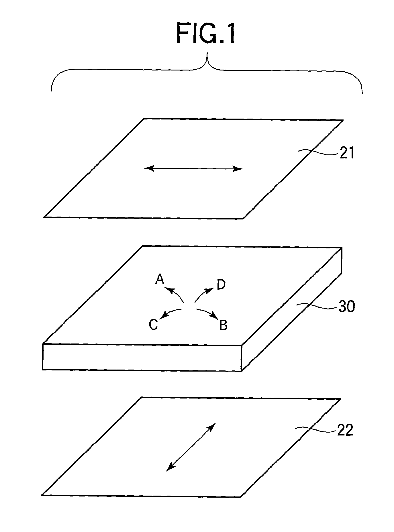
[0133] Prior to a description of an embodiment of the invention, a description will be made on an optical retardation film of a first type and an optical retardation film of a second type according to the invention.

[0134] FIG. 8 illustrates an optical retardation film. What is important for an optical retardation film is a retardation in an in-plane direction of the same and a retardation in the direction of the thickness, and the retardation in the in-plane direction and the retardation in the direction of the thickness are respectively expressed by:

Rp=(n.sub.x-n.sub.y)d;

[0135] and

Rt=((n.sub.x+n.sub.y) / 2-n.sub.z)d

[0136] where n.sub.x and n.sub.y represent refractive indices of the film in directions in the plane thereof, and n.sub.z represents a refractive index in the direction of the thickness of the same.

[0137] In the context of the invention, an optical retardation film in which n.sub.x is greater than both of n.sub.y and n.sub.z or which satisfies n.sub.x>n.sub.y, n.sub.z is r...

second embodiment

[0158] FIG. 6 shows a liquid crystal display 58 according to a second embodiment of the invention. The liquid crystal display 58 has a configuration similar to that of the liquid crystal display 56 in FIG. 5 except that the retardation R.sub.LC in the liquid crystal layer of the liquid crystal panel 30 is 350 nm and in that a second optical retardation film 54 of the second type is inserted between the second optical retardation film 52 of the first type and the second optical retardation film 46 of the second type. The optical retardation film 54 has a retardation of 55 nm in the direction of the thickness thereof, and the phase-delay axis of the same in the plane thereof is in parallel with the absorption axis of the polarizing element 44 located on the same side as the liquid crystal layer.

[0159] The sum Rp-t of retardations in direction in the plane of the liquid crystal display 58 is 70 nm, and the sum of retardations in the direction of the thickness is 285 nm. Equation 1 give...

third embodiment

[0162] FIG. 7 shows a liquid crystal display 59 according to a third embodiment of the invention. The liquid crystal display 59 has a configuration similar to that of the liquid crystal display 56 in FIG. 5 except that the retardation R.sub.LC in the liquid crystal layer of the liquid crystal panel 30 is 350 nm and that it has polarizers 31' and 40'. The polarizers 31' and 40' employ films 38 and 48 with a thickness in the range from 90 nm to 125 nm that have a retardation in the direction of the thickness greater than that in a normal TAC film (hereinafter referred to as "thick TAC films") as TAC films of protective layers to serve as optical retardation films of the second type. The use of such thick TAC films 38 and 48 is effective when a liquid crystal panel having a liquid crystal layer with a retardation R.sub.LC of about 350 nm is used as in the second embodiment. That is, there is no need for inserting any additional TAC film as an optical retardation film of the second type...


PUM


Abstract

There is provided a liquid crystal display which exhibits preferable viewing angle characteristics even in a diagonal viewing angle. Optical retardation films of a first type that satisfy nx>ny, nz and optical retardation films of a second type that satisfy nx=ny>nz are used, and a setting is made to satisfy Rp-t=2x(-0.08xRLC+58 nm+alpha) (alpha=±30 nm) and Rt-t=(1.05±0.05)xRLC-47 nm+beta(-100 nm<=beta<=47 nm) where DELTAnd represents a retardation RLC in the liquid crystal display; Rp-t represents the sum of retardations Rp in in-plane directions of a plurality of optical retardation films; and Rt-t represents the sum of retardations Rt in the direction of the thickness of the plurality of optical retardation films.

Description

[0001] 1. Field of the Invention[0002] The present invention relates to a liquid crystal display (LCD) and, more particularly, to a vertically aligned (VA) liquid crystal display in which liquid crystal molecules are aligned substantially vertically to the substrate when no voltage is applied to the liquid crystals and in which a phase difference film is used as a viewing angle compensation film to reduce viewing angle dependency that is characteristic of liquid crystal displays.[0003] 2. Description of the Related Art[0004] Liquid crystal displays, more particularly, TN (twisted nematic) display mode TFT (thin film transistor) LCDs utilizing the rotary mode have recently spread as displays for personal computers and the like. However, such TN LCDs have problems such as a reduction of display contrast in a diagonal viewing direction, inversion of brightness and darkness of display and an insufficient response speed. Under such circumstances, VA LCDs have been proposed which utilize ...

Claims


Application Information

Patent Timeline
IPC IPC(8): G02B5/30G02F1/1335G02F1/13363G02F1/1337G02F1/139
CPCG02F1/133634G02F1/1393G02F2413/105G02F1/13363
Inventor YOSHIDA, HIDEFUMISASABAYASHI, TAKASHITASAKA, YASUTOSHINAKANISHI, YOHEIOKAMOTO, KENJITANUMA, SEIJIHANAOKA, KAZUTAKAMAYAMA, TAKATOSHIINOUE, YUICHI
Owner SHARP KK
Why Eureka
Try Eureka