
Retention of a polishing pad on a platen

a technology for polishing pads and platens, which is applied in the direction of grinding machines, edge grinding machines, manufacturing tools, etc., can solve the problems of bulging bulges, raised areas or bulges in the polishing surface of the polishing pad, and air bubbles that tend to get trapped between the adhesive and the platen

Inactive Publication Date: 2001-10-18
RODEL HLDG INC
View PDF0 Cites 27 Cited by
  • Summary
  • Abstract
  • Description
  • Claims
  • Application Information

AI Technical Summary

Problems solved by technology

First, as the polishing pad is placed on the platen, bubbles of air tend to get trapped between the adhesive and the platen.
Any trapped air will distend the relatively thin polishing pad, thereby causing raised areas or bulges in the polishing surface of the polishing pad.
These bulges cannot be eliminated by forcing the air bubbles out from under the pad with a roller.
This is a time-consuming process, and some small bulges often go undetected and remain in the polishing surface.
Any bulges in the polishing surface will generate non-uniformities on the polished surface of the workpiece, thereby causing defects in the polished surface.
Another problem associated with the adhesive is that considerable force is required to pull a used polishing pad up from the platen for replacement, which work leads to strain injury to personnel.
Also, adhesive residue normally remains on the platen after the old polishing pad is pulled off.
Removing the residue is a time-consuming process which exposes personnel to potential chemical hazards.
Another problem is that the adhesive may release sodium and other ion bearing elements which interfere with semiconductor processing.

Method used


Image

  • Retention of a polishing pad on a platen
  • Retention of a polishing pad on a platen
  • Retention of a polishing pad on a platen

Examples


Embodiment Construction

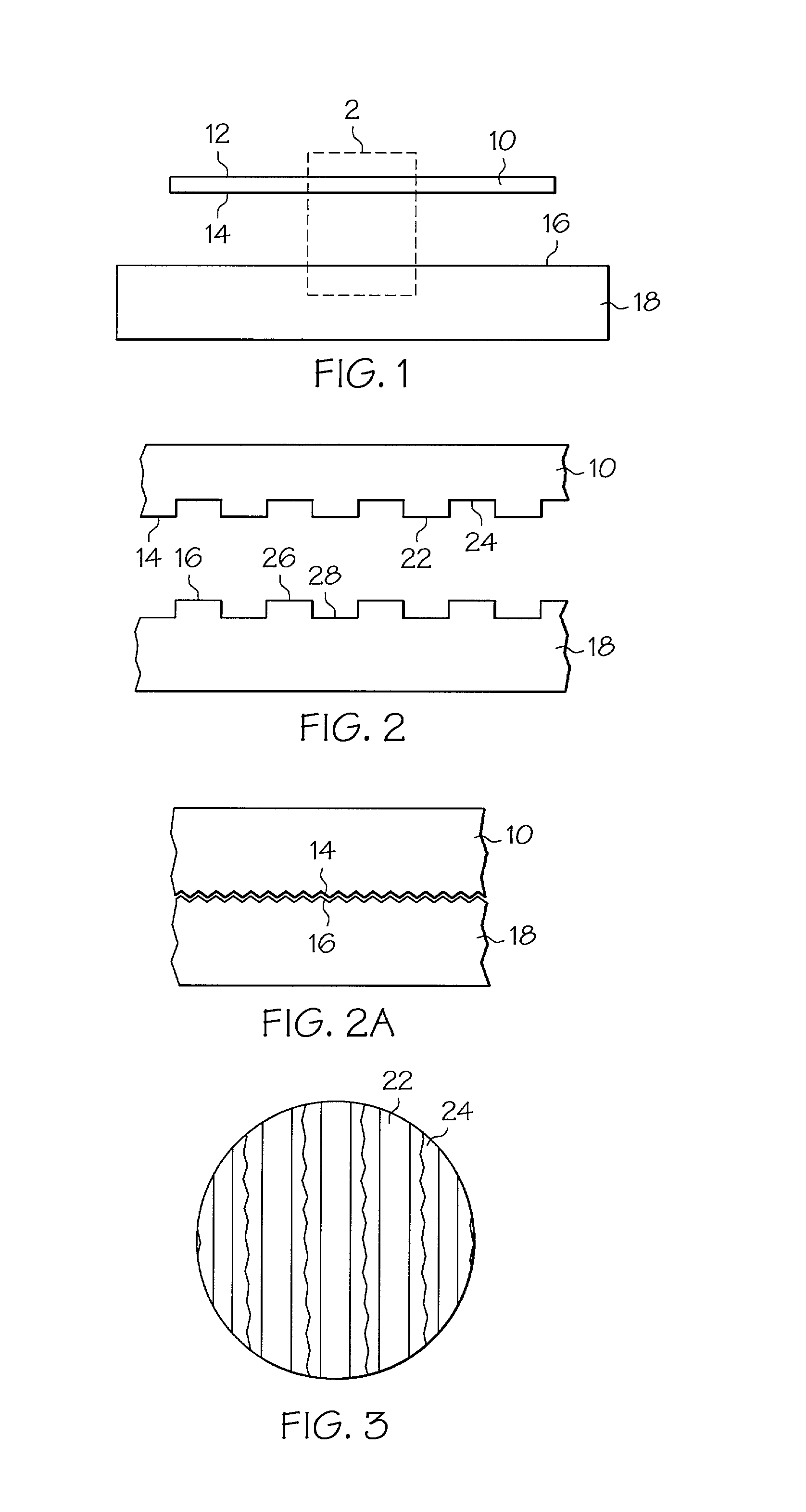
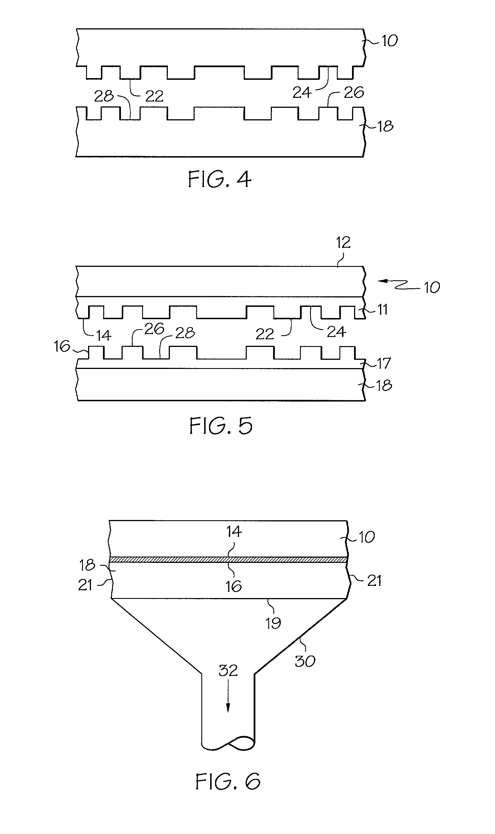
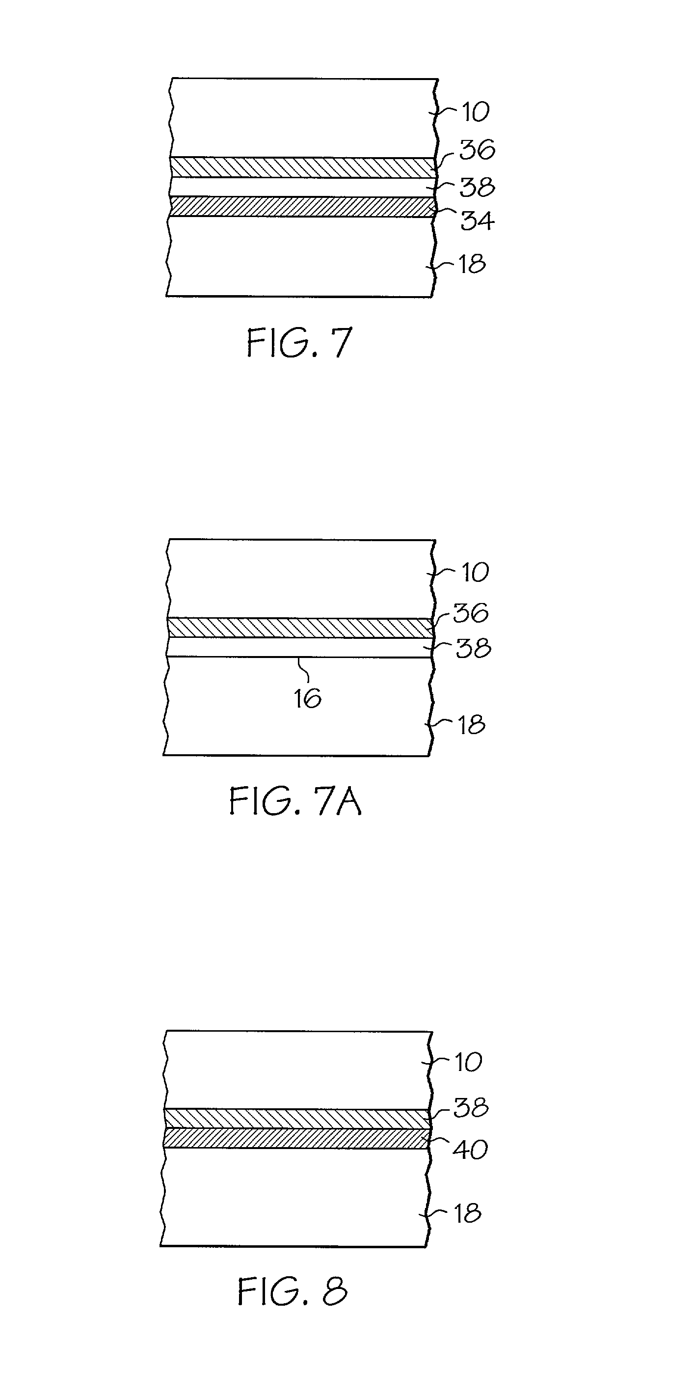
[0029] There is shown in FIG. 1 a polishing pad 10 comprising a top polishing surface 12 and an undersurface 14 that is adapted to be mounted on a front face 16 of a platen 18. The undersurface 14 has a profiled surface which is configured to interfit with a complementary profiled surface on the front face 16 of the platen.

[0030] In a preferred embodiment as shown in FIGS. 2 and 3, the undersurface 14 has a surface profile which includes an array of parallel ridges 22 and grooves 24, and the front face 16 has a surface profile which includes a complementary array of parallel ridges 26 and grooves 28. The ridges 22 and the grooves 24 are configured to interfit with the grooves 28 and the ridges 26, respectively, when the polishing pad is mounted on the platen.

[0031] The ridges 22, 26 are dimensioned for a close slip fit in respective ones of the grooves 24, 28. Preferably, the width of ridges 22, 26 differs slightly from the width of grooves 24, 28 in order to provide room for the ri...


PUM


Abstract

A polishing pad is retained on a platen by structures which do not require adhesive. In one embodiment, a polishing pad has a top polishing surface and an undersurface. The undersurface has a surface profile which is configured to interfit with a complementary surface profile on a platen. The surface profile of the undersurface may comprise an array of parallel ridges and grooves.

Description

[0001] 1. Field of the Invention[0002] The invention relates to device and method for securing a polishing pad on a platen of a polishing apparatus.[0003] 2. Discussion of Related Art[0004] Polishing pads for removing material from the surface of a workpiece are well-known. A typical polishing pad is a relatively thin, disk-shaped article that is mounted on a platen of a polishing machine. The polishing pad is generally secured to the platen by a pressure sensitive adhesive that is laminated on the back side of the polishing pad.[0005] The pressure sensitive adhesive has a number of disadvantages. First, as the polishing pad is placed on the platen, bubbles of air tend to get trapped between the adhesive and the platen. Any trapped air will distend the relatively thin polishing pad, thereby causing raised areas or bulges in the polishing surface of the polishing pad. These bulges cannot be eliminated by forcing the air bubbles out from under the pad with a roller. Instead, the bulge...

Claims


Application Information

Patent Timeline
IPC IPC(8): B24B37/16B24B37/26B24D9/08
CPCB24B37/16B24B37/26B24D9/085
Inventor SCOTT, DIANE B.LACK, CRAIG D.
Owner RODEL HLDG INC
Learn More