

Vehicle seat comprising a height-adjusting mechanism, and a control device for such a seat
- Summary
- Abstract
- Description
- Claims
- Application Information
AI Technical Summary
Benefits of technology
Problems solved by technology
Method used
Image

Examples
Embodiment Construction
[0028] In the different drawings, the same reference numbers refer to identical or similar elements.
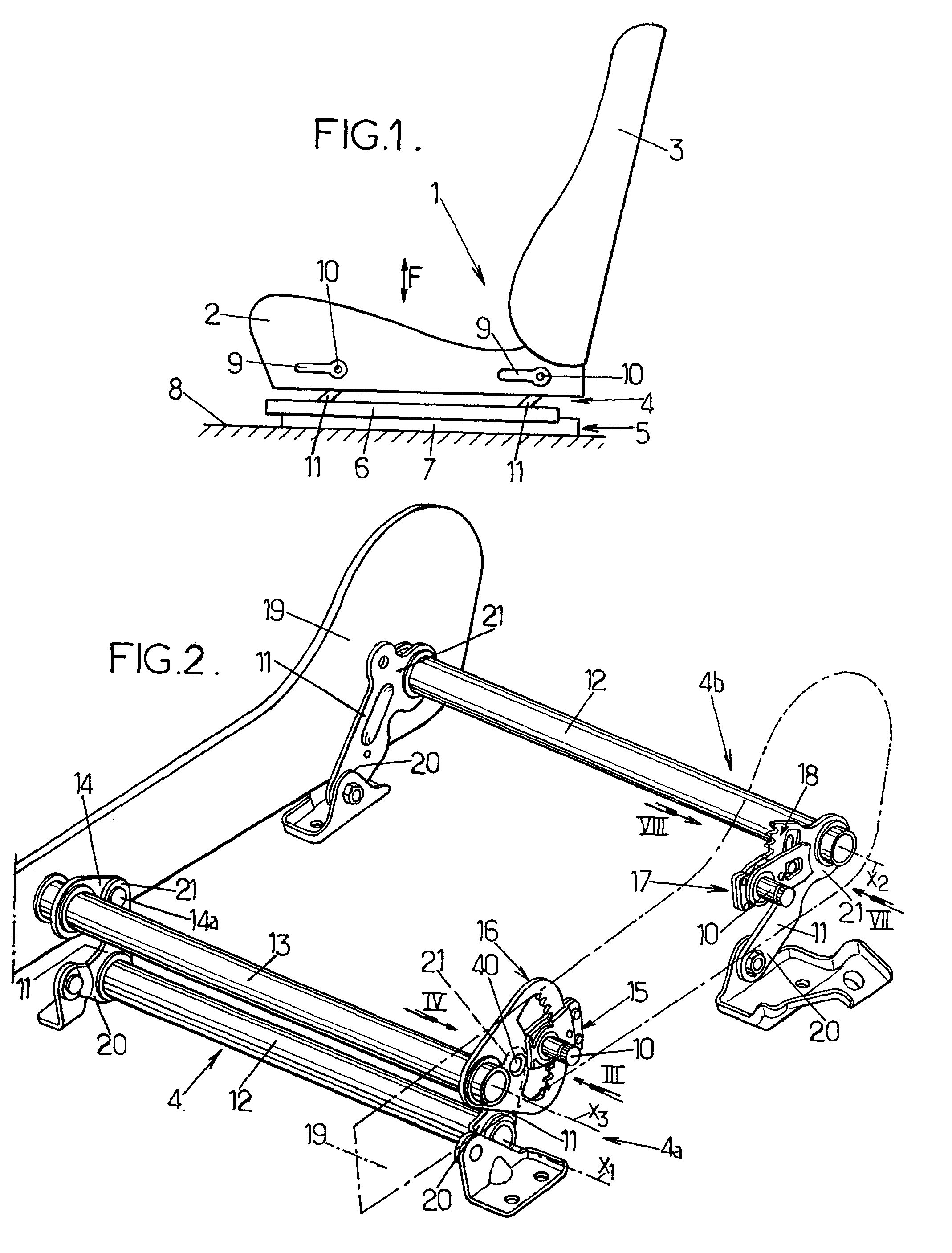
[0029] FIG. 1 shows a seat 1 of a motor vehicle comprising a cushion (seat part) 2 supporting a backrest 3 and itself supported by a height-adjusting mechanism 4 according to the present invention.
[0030] The height-adjusting mechanism 4 is mounted on the moving profile sections 6 of two longitudinal slides 5, only one of which is visible in FIG. 1, the two fixed profile sections 7 being integrally connected to the floor 8 of the vehicle.
[0031] The height-adjusting mechanism 4 comprises two hand levers 9 (one front lever and one rear lever) each of which is movable around a transverse horizontal axis 10 and controls the pivoting of metal links 11, the lower ends 20 of which are mounted pivotally to moving profile section 6 of the corresponding slide and the upper ends 21 of which are connected directly or otherwise to rigid plates 19 at the sides of the cushion, as shown in FIG. 2.
[003...
PUM
 Abstract
Description
Claims
Application Information