Position display system of mobile terminal

a technology of mobile terminals and display systems, applied in the field of mobile terminals, can solve problems such as inapplicability of systems, difficulty in drawing coverage, and inapplicability to systems

Inactive Publication Date: 2001-11-01
ACE COMP
View PDF0 Cites 74 Cited by
  • Summary
  • Abstract
  • Description
  • Claims
  • Application Information

AI Technical Summary

Benefits of technology

[0021] Another object of the present invention is to provide a mobile terminal that allows position detection at a low cost and at high accuracy.
[0022] A further object of the present invention is to provide a center apparatus that is employed in a position detection system of a mobile terminal at a low cost and at high accuracy.
[0023] Still another object of the present invention is to provide a system that allows automatic transmission of position information of a mobile terminal carried by a driver and the like to a center apparatus even when the driver is remote from a vehicle.

Problems solved by technology

However, it is difficult to draw the coverage contour in the frequency range used for a general mobile wireless telephone system and, therefore, it is not practical.
However, such a system cannot be applied to the system wherein the location of a man or a vehicle is detected with a precision of some 10 meters.
Since the driver is remote from the vehicle during the door delivery or reception, there is a possibility that an inquiry of the position of the vehicle from a wireless of the dispatch center is not responded.
The dispatch center may not easily catch a delivery vehicle near the client even though the client has urgent needs.
There was a problem that a complaint was filed of delayed service from customers.
Furthermore, the dispatch center must take the trouble to contact the driver of the mobile vehicle to have the driver's current location described orally in this MCA method.
This is not only tedious, but also places a considerable burden on the driver.
There was a problem that confirmation of the position information is troublesome.
However, such sign posts are installed only in the coverage area of the service vehicle.
Naturally, there is a limit in using this system over a wide area range.
There is also a problem that the sign post zone is so large that specification of the position of a mobile station becomes too rough to result in low precision of the position.
There is also a limit in reducing the size and weight of the mobile station since the output power of the transmitter is 1 W. There is also a problem that the position information of a mobile station must be transmitted to the center station through a taxi wireless and the like, which is rather tedious.
Furthermore, extension of the sign posts causes increase in the facility cost.
Reduction in size, weight, and cost as a terminal system cannot be achieved.
However, the coverage area is extremely limited with such a weak wave that is allowed according to the current Wireless Telegraphy Act.
Such position confirmation devices are not practical.

Method used


Image

  • Position display system of mobile terminal
  • Position display system of mobile terminal
  • Position display system of mobile terminal

Examples


first embodiment

[0076] (A) First Embodiment

[0077] Embodiments of the present invention will be described hereinafter with reference to the drawings. The first embodiment will be described in which a small zone wireless communication system such as a PHS (simple portable telephone) is used.

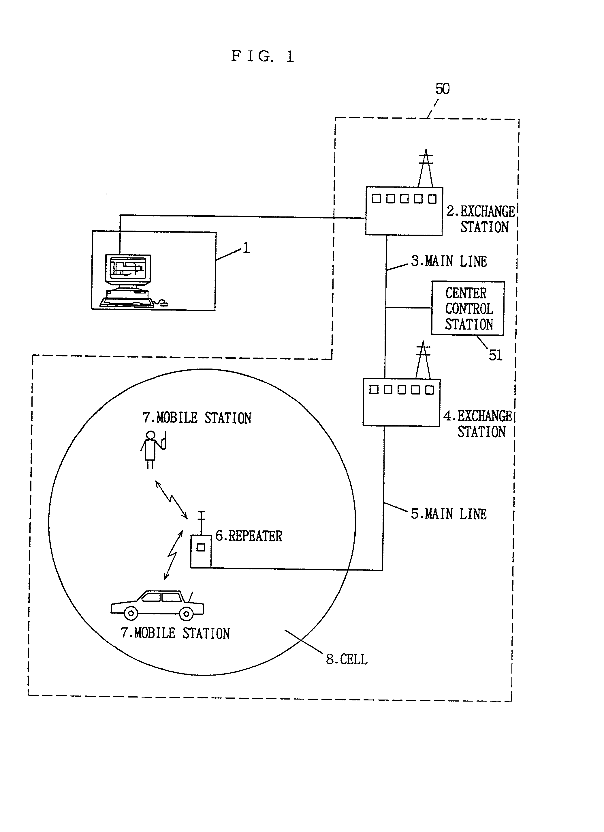
[0078] A portable terminal of the PHS (referred to as "mobile station" hereinafter) is generally used as a cordless telephone at home. It can be used outside the house to be connected to a public network or a digital network via an indoor public repeater or an outdoor public repeater. In other words, it can be literally used as a handy portable telephone. The PHS greatly differs from the existing cellular type portable telephones (here, the existing portable telephone system will be generically referred to as the cellular system) in that the PHS is implemented based on a small zone system. A cellular type portable telephone has an output of at least 600 mW as a mobile station with a repeater installed for every re...

second embodiment

[0115] (B) Second Embodiment

[0116] In the second embodiment, the small zone wireless communication system (including wireless telephone) such as the PHS shown in FIG. 1 is used. In the communication between repeater 6 and mobile station 7, a transmission identification code (CS-ID) and a reception identification code (PS-ID) as shown in FIGS. 5 and 6 are transmitted therebetween regardless of whether the system is a public system including a center station 1, exchange stations 2 and 4 of a public network, a digital network, and the like, repeater 6, and mobile station 7, or a self-management system.

[0117] FIG. 5 shows an exemplary structure of a transmission identification code and a reception identification code for transmission between a repeater (CS) 6 and a mobile station (PS) 7 in a self-management system. Referring to FIG. 5, a transmission identification code specifying a repeater is formed of 42 bits, including a 29-bit system call code representing a calling code of the sel...

third embodiment

[0130] (C) Third Embodiment

[0131] A third embodiment of the present invention will be described hereinafter. Similar to the first and second embodiments, the small zone wireless communication system such as the PHS is employed in the third embodiment.

[0132] FIG. 16 is a schematic diagram showing wave propagation pattern information of center station 1 according to the third embodiment. The left side represents a three dimensional map shown in map 10, and the right side represents the wave propagation pattern thereof. (A) indicates the case where repeater 6 is installed in the proximity of a crossroad, (B) indicates the case where repeater 6 is installed at a straight road, and (C) shows the case where repeater 6 is installed in the proximity of a forked road. FIG. 17 shows the wave propagation pattern where there is a building at one side and a park at the other side of a straight road.

[0133] In the third embodiment, such information is stored in CD-ROM 65 of center station 1 and in...


PUM


Abstract

A position detection system of a mobile terminal includes a small zone communication system (50) such as the PHS system, and a center station (1) connected to an exchange station (2) forming the PHS system. When a call is dispatched from the center station to the telephone number of a mobile station 7 of which the position is to be identified, the call signal is transmitted to a repeater (6) located closest to the mobile station (7) via exchange stations (2, 4) and main lines (3, 5) forming the PHS system (50). Since the mobile station (7) can identify the identification number of the closest repeater (6), the position of repeater (6) can be identified by referring to the database of the PHS system (50) using the repeater database provided in a center control station (51). The position can be displayed on a CRT screen at the center station (1) side. A position detection apparatus of a mobile terminal that can detect a position at low cost and at high accuracy is provided.

Description

[0001] 1. Field of the Invention[0002] The present invention relates to a position display system of a mobile terminal, a center station therefor, and a mobile terminal thereof. Particularly, the present invention relates to a position display apparatus of a mobile terminal employing a small zone communication system, a system therefor, and a mobile terminal thereof.[0003] 2. Description of the Background Art[0004] A method of detecting the position of a mobile of interest to the present invention is disclosed in Japanese Patent Publication No. 6-93650, for example. According to the present publication, waves from a plurality of repeaters are received at respective mobiles in a mobile communication system for carrying out communication between a repeater and a mobile via a wave. By using a coverage contour of a reception electric field level from each repeater obtained in advance, the range in which a mobile can be located corresponding to each reception level is obtained to detect ...

Claims


Application Information

Patent Timeline
Patent Type & Authority Applications(United States)
IPC IPC(8): G01S19/25H04W4/90H04W16/26H04W60/00H04W64/00H04W88/18
CPCH04B7/2606H04W4/22H04W16/26H04W88/18H04W64/00H04W76/007H04W60/00H04W76/50H04W4/90H04W4/029H04W8/02H04W8/08H04W60/04H04W4/33
Inventor KOSHIMA, HIROAKIKUMAMOTO, KATSUHIKOMUYA, KIMIOKUROKAWA, HIROYUKIIWAGAMI, RYUICHI
Owner ACE COMP
Why Eureka
Try Eureka