Line scanning type ink jet recording device capable of finely and individually controlling ink ejection from each nozzle

a recording device and ink jet technology, applied in the direction of printing, electrical equipment, pictoral communication, etc., can solve the problems of affecting the quality of printing,

Inactive Publication Date: 2001-11-08
RICOH PRINTING SYST
View PDF3 Cites 31 Cited by
  • Summary
  • Abstract
  • Description
  • Claims
  • Application Information

AI Technical Summary

Problems solved by technology

However, it is difficult and expensive to produce an accurate print head with such a large number of nozzles without causing unevenness among the nozzles.
Uneven nozzles undesirably degrade printing quality.
Moreover, even if a precise print head is produced, unevenness may occur among the nozzles over time of use.
However, the dots 402 through 405 are formed at in an undesirable manner.
When

Method used


Image

  • Line scanning type ink jet recording device capable of finely and individually controlling ink ejection from each nozzle
  • Line scanning type ink jet recording device capable of finely and individually controlling ink ejection from each nozzle
  • Line scanning type ink jet recording device capable of finely and individually controlling ink ejection from each nozzle

Examples


first embodiment

[0047] First, an overall configuration of a printer according to the present invention will be described while referring to FIGS. 4, 5, and 8.

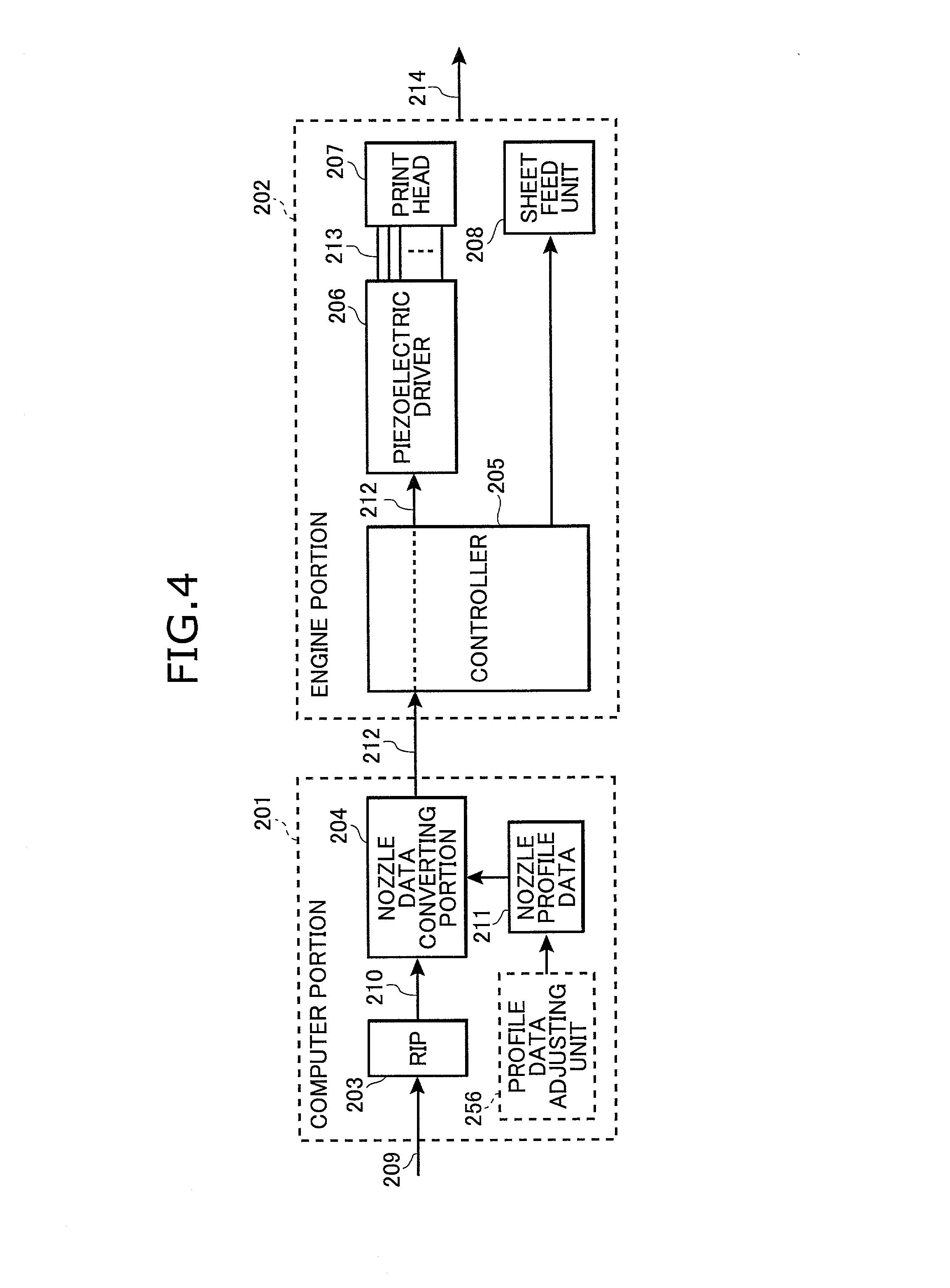
[0048] As shown in FIG. 4, the printer includes a computer portion 201 and an engine portion 202. The computer portion 201 includes a memory storing a printer driver software 201a and nozzle profile data 211. The printer driver software 201a includes a raster image processor (RIP) 203 and a nozzle data converting portion 204. The engine portion 202 includes a controller 205, a piezoelectric driver 206, a print head 207, and a sheet feed unit 208.

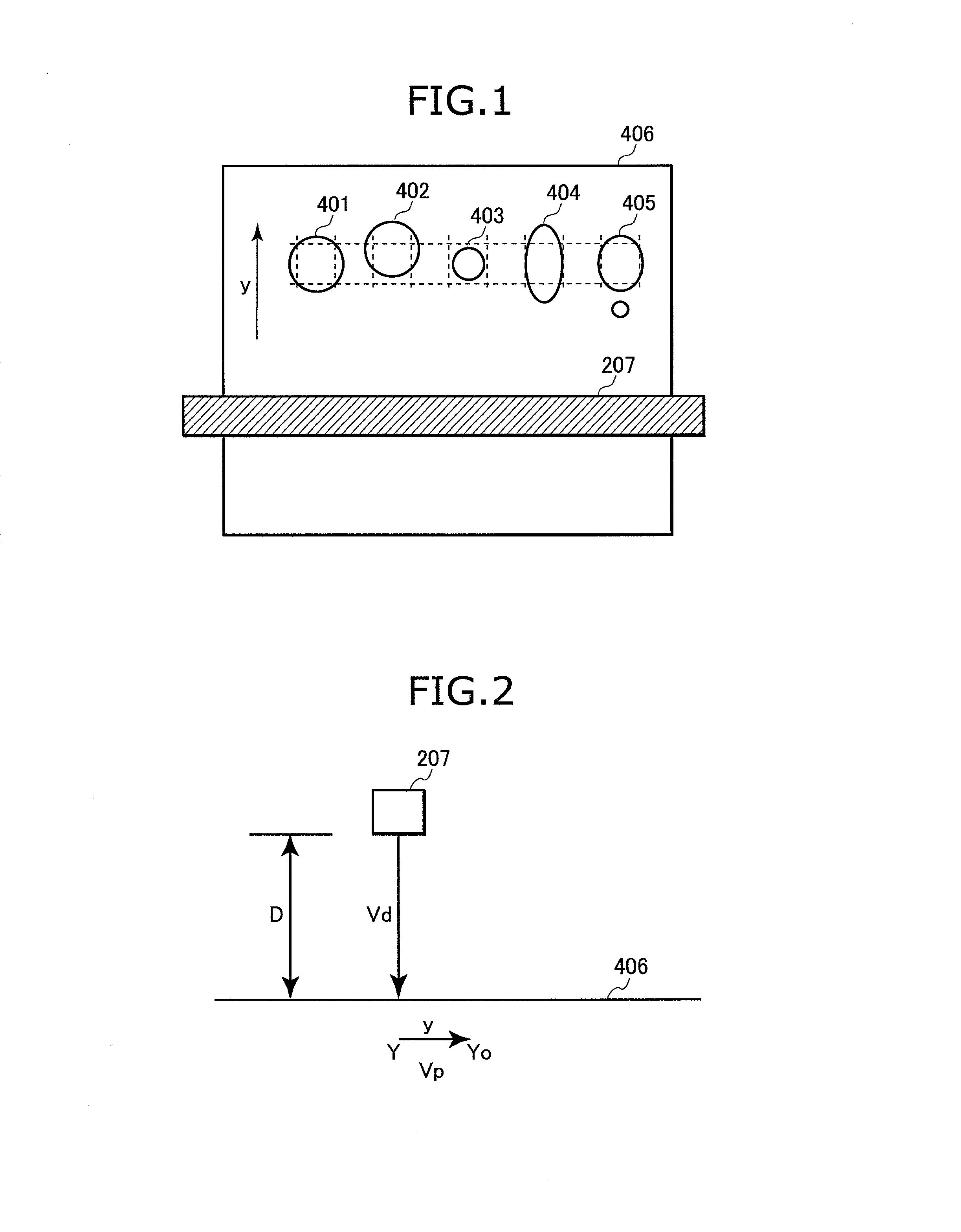
[0049] FIG. 8 shows an ink ejection surface 312a of the print head 207. The print head 207 is formed with a plurality of nozzles 207a. A center position of each nozzle 207a is expressed by the x and y coordinate axis in a unit of length (.mu.m). It should be also noted that a recording sheet is transported in the y direction in the present embodiment.

[0050] The engine portion 202 is designed for printi...

second embodiment

[0085] In order to overcome these problems, the printer of the second embodiment changes the ink ejection amount m by dividing each driving pulse into a plurality of sub-pulses in the following manner.

[0086] FIG. 12(b) shows a driving pulse divided into two sub-pulses at its center by a voltage non-application time having a time width of Tsplit (.mu.s). FIG. 12(a) shows a graph F3 showing relationships between the Tsplit and an ejection speed Vd(m / s) and between the Tsplit and an ink ejection amount m (ng). In the present example, the time width Tw of the driving pulse is set to Tn / 2, that is, 9 .mu.s. The profile data update unit 101 determines the pulse data 1 based on both the target ink ejection amount M and the graph F3 which indicates the relationship between the Tsplit and the ink ejection amount m, and updates the nozzle profile data 211, in a similar manner as in the above-described first embodiment.

[0087] An example is shown in FIG. 18. It should be noted that the time wid...

third embodiment

[0093] Next, the present invention will be described while referring to FIGS. 11, 12, 14, 15, and 16, and 11.

[0094] In the above-described first and second embodiments, it is assumed that the print head 207 ejects an ink droplet along a normal line in a direction perpendicular to the nozzle surface 312a. However, an actual ink droplet is ejected in a direction slightly angled with respect to the normal line toward the y direction and / or x direction. The angle of the ink ejection with respect to the normal line differ among the nozzles 207a. Accordingly, impact positions shift from a target impact position with respect to the y and x directions because of the slight difference between the actual ink ejection direction and the direction in which the normal line extends.

[0095] The printer of the third embodiment corrects error on impact position caused by such a direction difference for each nozzle 207a.

[0096] The printer of the third embodiment includes a print head 1207 shown in FIGS...


PUM


Abstract

A computer portion 201 of a printer includes a memory storing a printer driver software 201a and nozzle profile data 211. The printer driver software 201a includes a raster image processor (RIP) 203. When the RIP 203 receives document data 209, the RIP 203 converts the document data 209 into bitmap data 210 which is one dot/one bit data for 300 data/inch. Then, the nozzle data converting portion 204 converts the bitmap data 210 into driving data 212 based on the nozzle profile data 211. At this time, each bit of the bitmap data 210 is replaced by 16 bits. That is, the data amount is increased to 16 times of the bitmap data 210. Accordingly, fine control of ink ejection can be achieved.

Description

[0001] 1. Field of the Invention[0002] The present invention relates to a dot-on-demand type ink jet printer including piezoelectric elements capable of reliably printing high quality images at high speed.[0003] 2. Related Art[0004] There has been proposed a dot-on-demand type image forming device. Although the dot-on-demand type image forming device is relatively slow in printing speed compared with a continuous type image forming device, the dot-on-demand type image forming device has a simple configuration, so has become more popular.[0005] Japanese Patent Application Publication (Kokai) No. HEI-11-78013 discloses a dot-on-demand line-scanning type ink jet recording device including a print head. The print head has a width corresponding to an entire width of a recording sheet, and is formed with a plurality of nozzles arranged in a line. Each nozzle is provided with an ejection element, such as a piezoelectric element or thermal element. The ejection elements are selectively driv...

Claims


Application Information

Patent Timeline
IPC IPC(8): B41J2/045B41J2/055B41J2/075B41J2/13B41J2/21H04N1/034H04N1/23
CPCB41J2/075B41J2/2135
Inventor KOBAYASHI, SHINYAYAMADA, TAKAHIROSHIMIZU, KAZUOSATOU, KUNIOKIDA, HITOSHI
Owner RICOH PRINTING SYST
Why Eureka
Try Eureka