Fringe field switching mode liquid crystal display

a switching mode and liquid crystal display technology, applied in non-linear optics, instruments, optics, etc., can solve the problems of high production cost, difficult to eliminate electrostatic and afterimage, and high production cost of ffs mode lcd

Inactive Publication Date: 2001-12-06
BOE HYDIS TECH
View PDF0 Cites 59 Cited by
  • Summary
  • Abstract
  • Description
  • Claims
  • Application Information

AI Technical Summary

Problems solved by technology

However, the FFS mode LCD has a disadvantage of high production cost due to an over coating layer (14) formed on the upper substrate.
And, the FFS mode LCD has a difficulty in realizing a high quality screen since a counter electrode and a pixel electrode are all disposed on a lower substrate, therefore it is difficult to eliminating electrostatic and afterimage.

Method used


Image

  • Fringe field switching mode liquid crystal display
  • Fringe field switching mode liquid crystal display
  • Fringe field switching mode liquid crystal display

Examples


Embodiment Construction

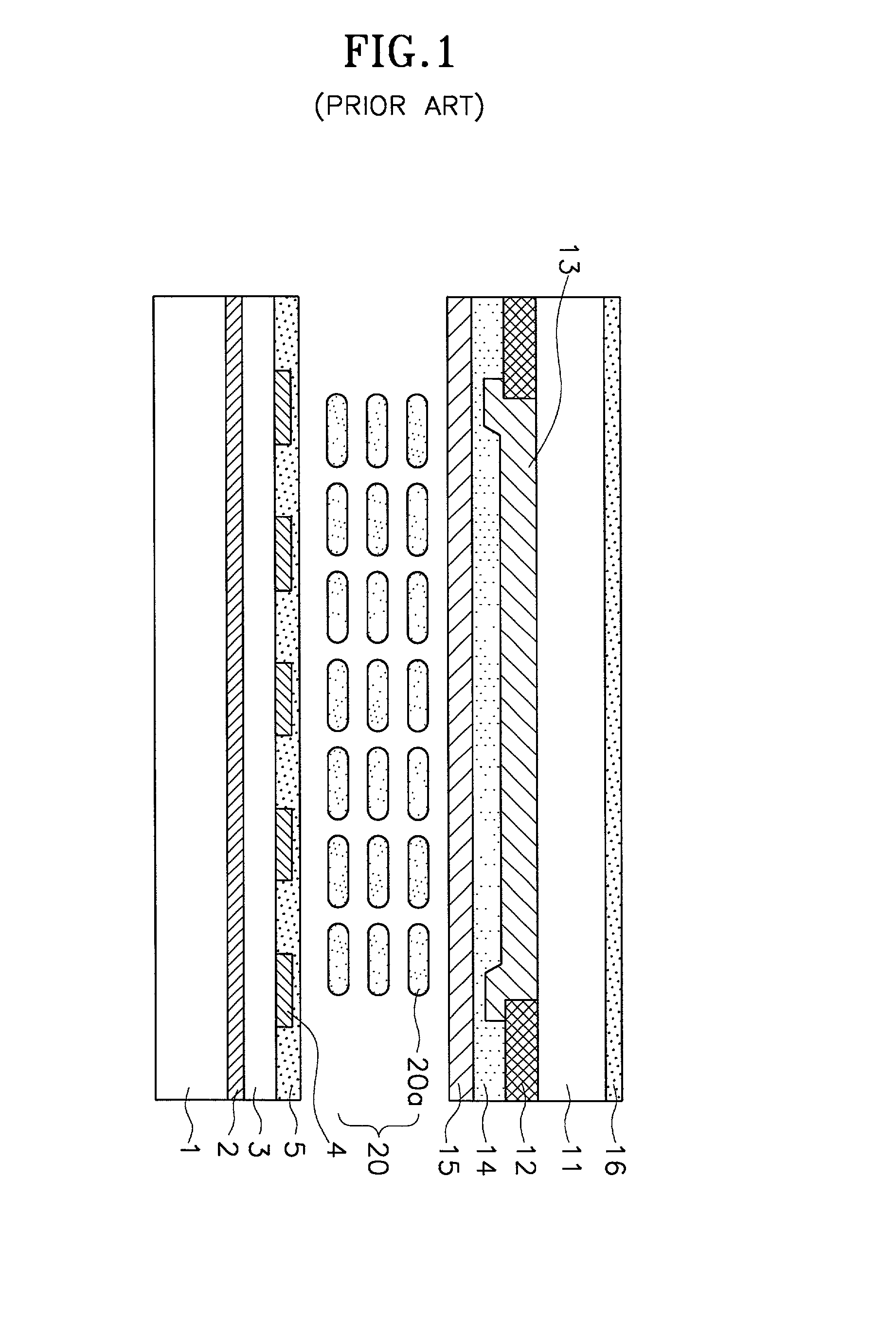
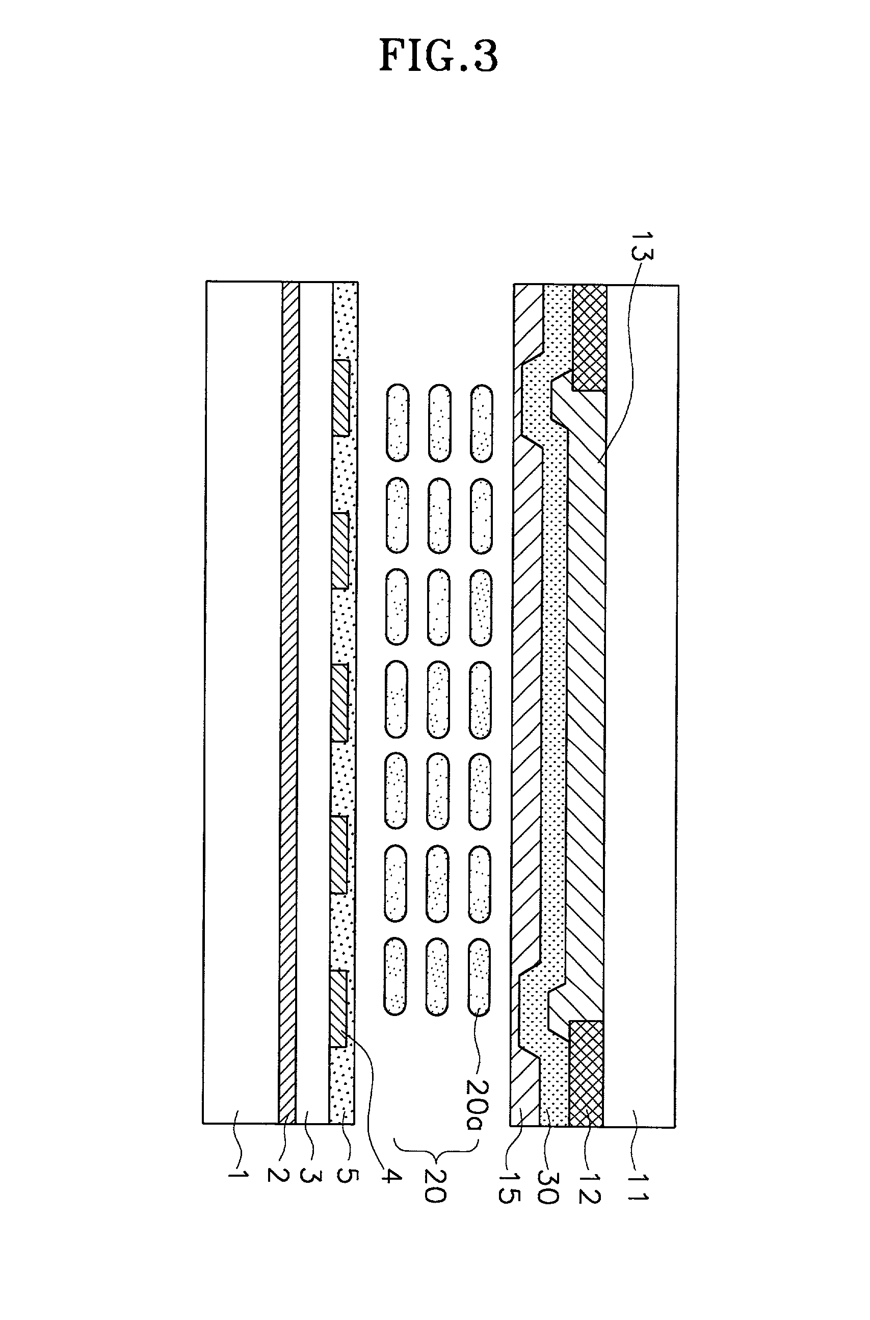
[0032] FIG. 3 is a cross-sectional view of FFS mode LCD according to a preferred embodiment of the present invention. The same parts as FIG. 1 are referred as the same drawing codes.

[0033] A lower substrate (1) and an upper substrate (11) are first disposed opposite to each other at a predetermined distance (d). The lower and upper substrates (1,11) are transparent insulating substrates, such as glass substrates. A liquid crystal layer (20) comprising a plurality of liquid crystal molecules (20a) of negative dielectric anisotropy is then interposed between the substrates (1,11).

[0034] A plurality of gate bus lines and data bus lines (not illustrated) are cross-arranged on the inner surface of the lower substrate (1). A TFT (not illustrated) is disposed at the intersection of the lines. A counter electrode (2) and a pixel electrode (4) comprising transparent conductors, such as ITO, are disposed in the pixel region defined by the gate bus line and the data bus line with a gate insula...


PUM

PropertyMeasurementUnit
widthaaaaaaaaaa
widthaaaaaaaaaa
transmittanceaaaaaaaaaa

Abstract

The present invention discloses a fringe field switching mode liquid crystal display. The disclosed comprises: a lower and an upper substrates disposed opposite to each other at a predetermined distance, having transparency; a counter electrode and a pixel electrode disposed on the inner surface of the lower substrate with a gate insulating layer interposed and made of transparent conductors, forming a fringe field when a electric field is applied; a black matrix and color filter formed on the inner surface of the upper substrate; an ITO layer disposed on the inner surface of the upper substrate which has the black matrix and the color filter therein; and a liquid crystal layer interposed between the lower and the upper substrates, including a plurality of liquid crystal molecules of negative dielectric anisotropy. In the FFS mode LCD of the present invention, the counter electrode has a plate shape and the pixel electrode has a slit shape. And the counter electrode has one or more grooves whose width is smaller than that of the slit of the pixel electrode, preferably 2 or 3 mum and the ITO layer includes a window region therein.

Description

[0001] 1. Field of the Invention[0002] The present invention relates to a fringe field switching mode liquid crystal display, and more particularly a fringe field switching mode liquid crystal display realizing a high quality screen and reducing production cost at the same time.[0003] 2. Description of the Related Art[0004] An In-Plane Switching (IPS) mode LCD has been proposed in order to improve a narrow viewing angle of TN mode LCD. This IPS mode LCD has an improved viewing angle by a structure that a counter electrode and a pixel electrode for driving liquid crystal are disposed on an array substrate and only a major axis is to be seen regardless of the viewing direction.[0005] As described above, the IPS mode LCD has an improved viewing angle, however, it has a low aperture ratio and transmittance since the counter and pixel electrodes are formed of opaque metals. Therefore, a fringe field switching mode LCD (hereinafter referred as FFS mode LCD) has been pro posed in order to ...

Claims


Application Information

Patent Timeline
Patent Type & Authority Applications(United States)
IPC IPC(8): G02F1/1335G02F1/1333G02F1/1337G02F1/1343
CPCG02F1/134363G02F2201/121G02F1/136
Inventor KIM, HYANG YULLEE, SEUNG HEEHONG, SEUNG HO
Owner BOE HYDIS TECH
Why Eureka
Try Eureka