Connecting structure for battery terminals

a battery terminal and connection structure technology, applied in the direction of cell components, cell component details, coupling device connections, etc., can solve the problems of high-voltage batteries, increase the seriousness of problems, and electrical backflow

Inactive Publication Date: 2001-12-20
YAZAKI CORP
View PDF0 Cites 21 Cited by
  • Summary
  • Abstract
  • Description
  • Claims
  • Application Information

AI Technical Summary

Problems solved by technology

Thus, there is a fear that electric backflow caused by the miscontact may break the equipment.
However, the implementation of a high-voltage battery increases the degree of seriousness of the problems of accidents due to the miscontact and sparks due to an arc.
Furthermore, recent increase in the power consumption of per vehicle results in increase in the number of batteries mounted on a vehicle.
Even when the battery terminal is misfitted into the terminal accommodation space of the terminal cover that does not correspond to this battery terminal, this battery terminal cannot be fitted thereinto owing to the difference in the shape therebetween.
Further, even when the terminal cover having accommodated and held the battery terminal is misplaced at the fastening / fixing position on the battery electrode of the polarity that does not correspond to the terminal cover, the fitting projection piece of the terminal cover cannot be fitted to the cover fitting hole of the battery body owing to the difference in the configuration, such as the opening shape and the position, between the fitting projection piece and the fitting hole.
Moreover, even the contact between the battery terminal, which is surrounded by the terminal cover, and the battery electrode of the polarity, which does not correspond to the battery terminal, cannot be achieved.
Thus, even when each of the terminal covers respectively accommodating and holding the corresponding battery terminals is misplaced at the fastening / fixing positions on one of the battery electrodes, which is of the polarity that does not correspond thereto, the fitting concave portion of this terminal cover cannot be fitted thereonto because of the difference in shape between the corresponding battery electrode and the corresponding pedestal.

Method used


Image

  • Connecting structure for battery terminals
  • Connecting structure for battery terminals
  • Connecting structure for battery terminals

Examples


Embodiment Construction

[0035] Hereinafter, a connecting structure for battery terminals according to an embodiment of the invention is described in detail with reference to the accompanying drawings.

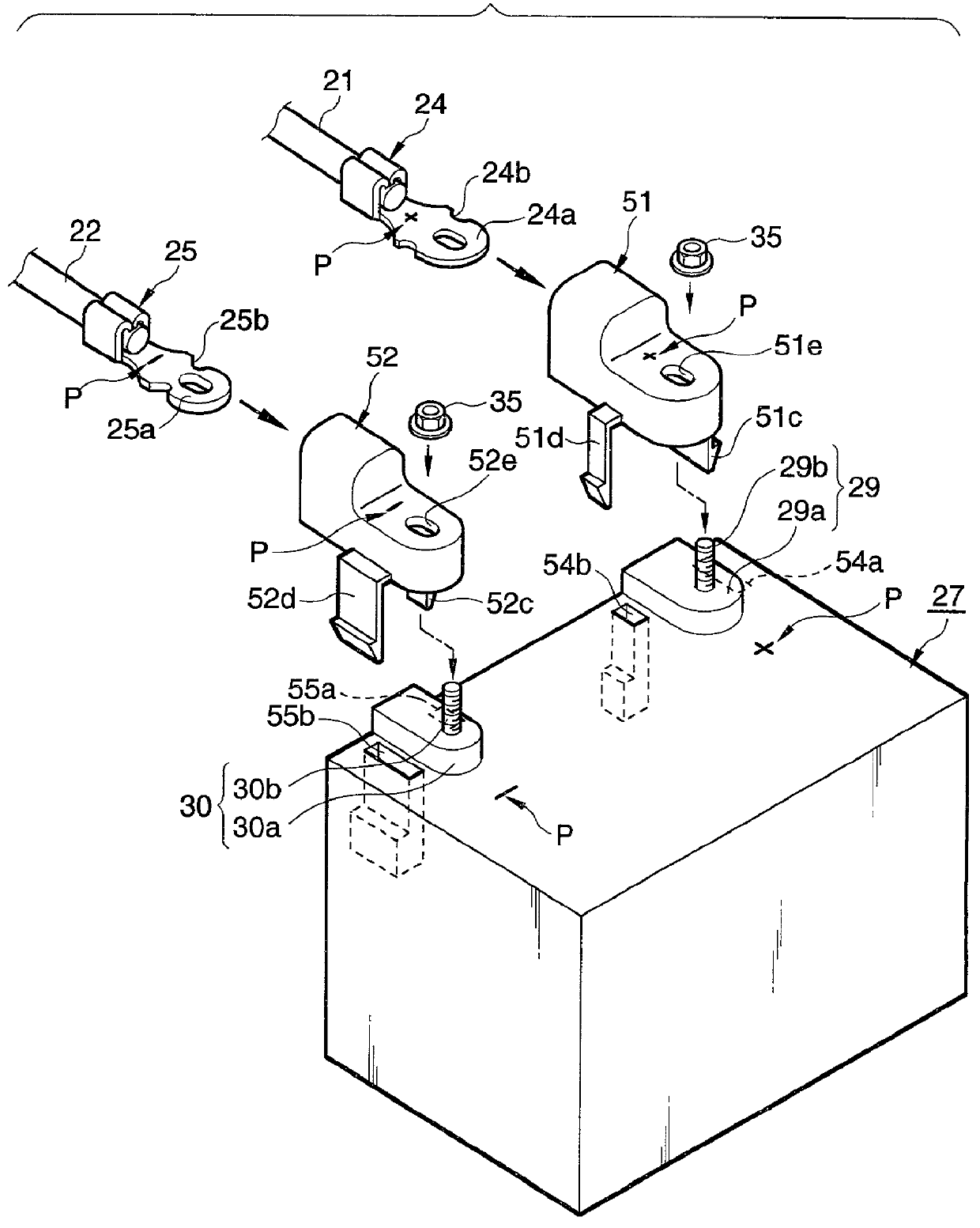
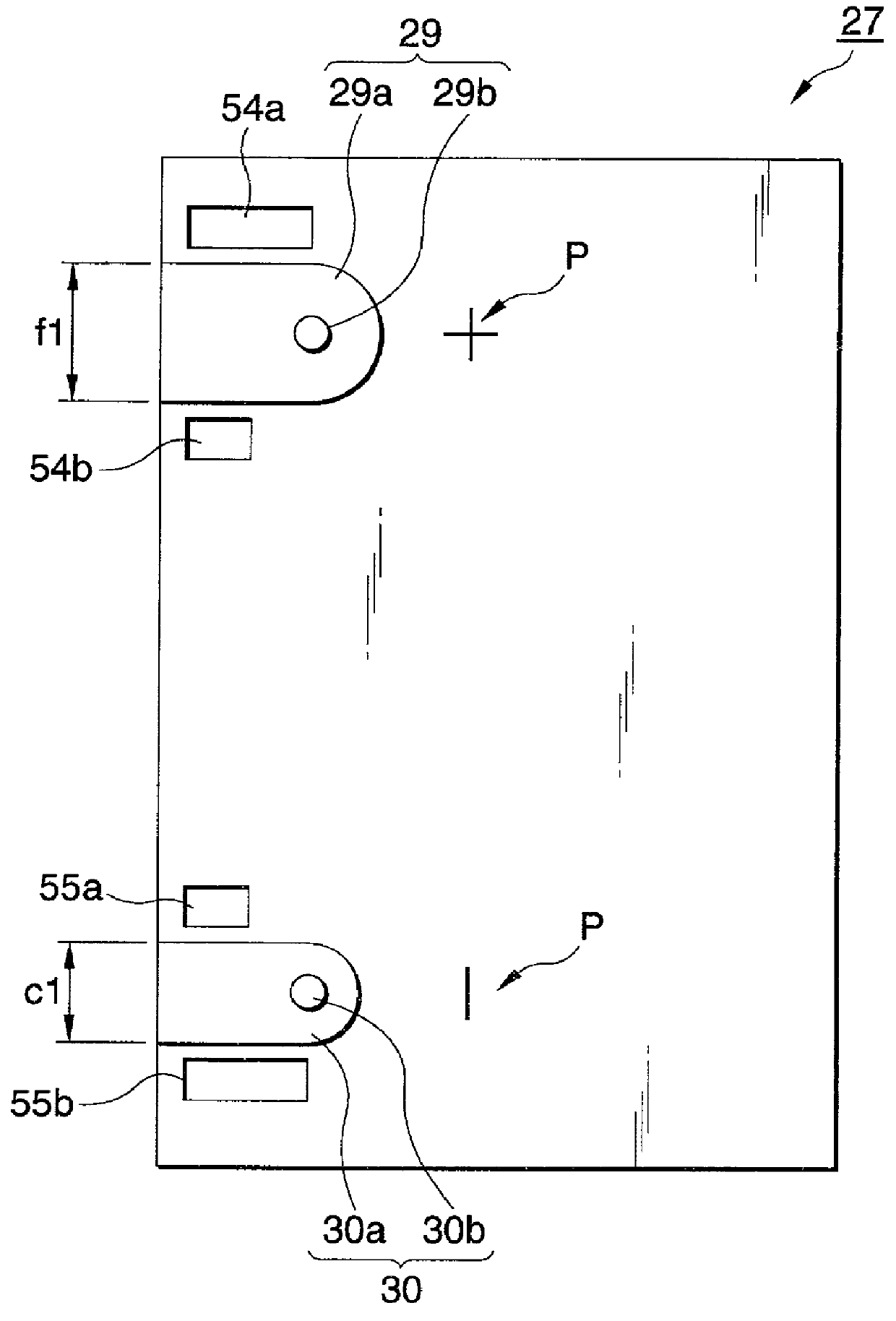
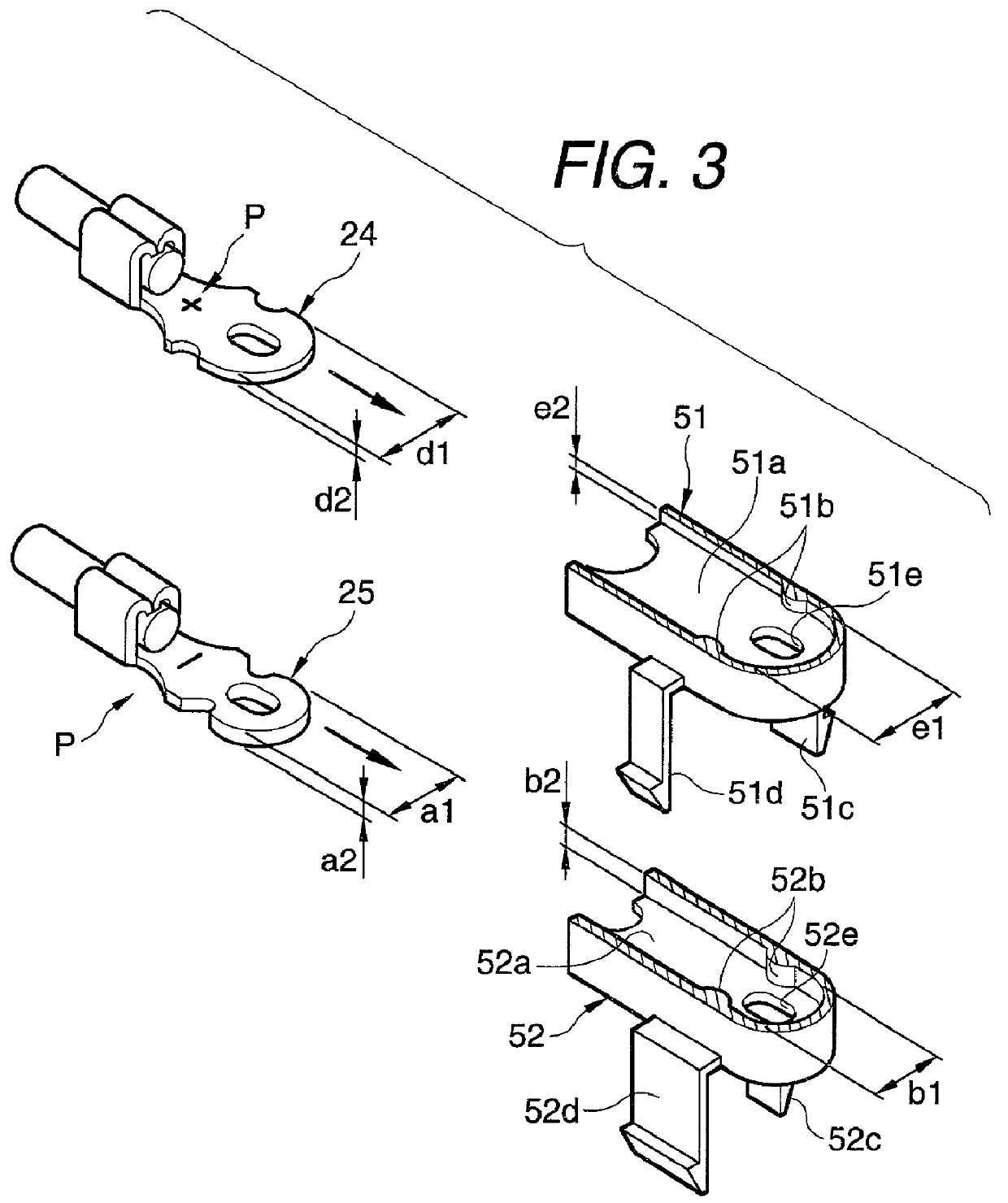
[0036] FIG. 1 is a perspective view illustrating the entire battery body having a connecting structure for a battery terminal according to a first embodiment of the invention. FIG. 2 is a plan view illustrating the battery body shown in FIG. 1. FIG. 3 is a partially broken perspective view of the internal structure of a primary part of the terminal cover shown in FIG. 1.

[0037] As shown in FIG. 1, the connecting structure for battery terminals is adapted to establish the electrical connection between battery terminals and battery electrodes by fastening and fixing each of the battery terminals 24, 25 to one of the battery electrodes 29, 30 by using a nut 35 serving as a screw member. The battery terminals 24, 25 respectively correspond to the positive polarity and the negative polarity and are connected to the ...


PUM

PropertyMeasurementUnit
electricalaaaaaaaaaa
shapesaaaaaaaaaa
distanceaaaaaaaaaa

Abstract

Terminal covers (51, 52) have terminal accommodation spaces, each of which has an opening of a predetermined shape that permits only one of battery terminals (24, 25), which is of predetermined polarity, to be fitted thereto. Each of the battery terminals (24, 25) is formed in such a manner as to have a predetermined shape enabling the battery terminal to be fitted into the corresponding terminal accommodation space. The battery body (27) has cover fitting holes (54a, 54b (55a, 55b)), which permit only fitting projection pieces (51c, 51d (52c, 52d)) of the terminal cover (51 (52)) accommodating and holding the battery terminal (24 (25)) to be fitted thereinto, in the vicinity of the battery electrode (29 (30)) so that only the battery terminal (24 (25)) is placed at a fastening/fixing position on the battery electrode (29(30)). Each of the fitting projection pieces (51c, 51d (52x, 52d)) is formed in such away as to have a predetermined shape that permits these pieces can be fitted into the corresponding cover fitting holes (54a, 54b (55a, 55b)).

Description

[0001] 1. Technical Field of the Invention[0002] The present invention generally relates to a connecting structure for battery terminals and, more particularly, to a connecting structure for surely connecting battery terminals to battery electrodes of corresponding polarity of a battery body mounted on a vehicle without miscontact of the battery terminals with the battery electrode.[0003] 2. Related Art[0004] FIGS. 5 and 6 illustrate a related connecting structure for fastening and fixing battery terminals, provided at an end of an electric wire connected to various kinds of electrical equipment, to battery electrodes of a battery body, mounted on a vehicle, by screw members.[0005] This connecting structure for a battery terminal is disclosed in JP-A-4-220947, and configured so that a positive battery electrode 3 and a negative battery electrode 4 of the vehicle-mounted battery body 1 are quadrangular-prism-like posts 3b and 4b respectively erected on base potions 3a and 4a on the t...

Claims


Application Information

Patent Timeline
Patent Type & Authority Applications(United States)
IPC IPC(8): H01M2/30H01M2/34H01R11/28H01R13/642
CPCH01R11/282H01R11/284H01R13/642
Inventor TAMAI, YASUHIROGOHARA, TAKASHIHASEGAWA, TETSUYA
Owner YAZAKI CORP
Why Eureka
Try Eureka