Blower

a technology of blower and cylinder head, which is applied in the direction of positive displacement liquid engine, piston pump, liquid fuel engine, etc., can solve the problems of difficult to incorporate the compressed spring 106 into the clearance, complicated assembly operation, and difficulty in setting such distances

Inactive Publication Date: 2002-01-24
MINEBEA CO LTD
View PDF0 Cites 146 Cited by
  • Summary
  • Abstract
  • Description
  • Claims
  • Application Information

AI Technical Summary

Problems solved by technology

However, in the case of the pre-loading means as shown in FIG. 9, the clearance defined between the yoke 105 and the ball bearing 102 is very narrow, making it difficult to incorporate the compressed spring 106 into the clearance.
Further, the necessity of incorporation of the spring into the clearance upon assembling the blower will make the assembling operation complic

Method used


Image

  • Blower
  • Blower
  • Blower

Examples


first embodiment

The First Embodiment

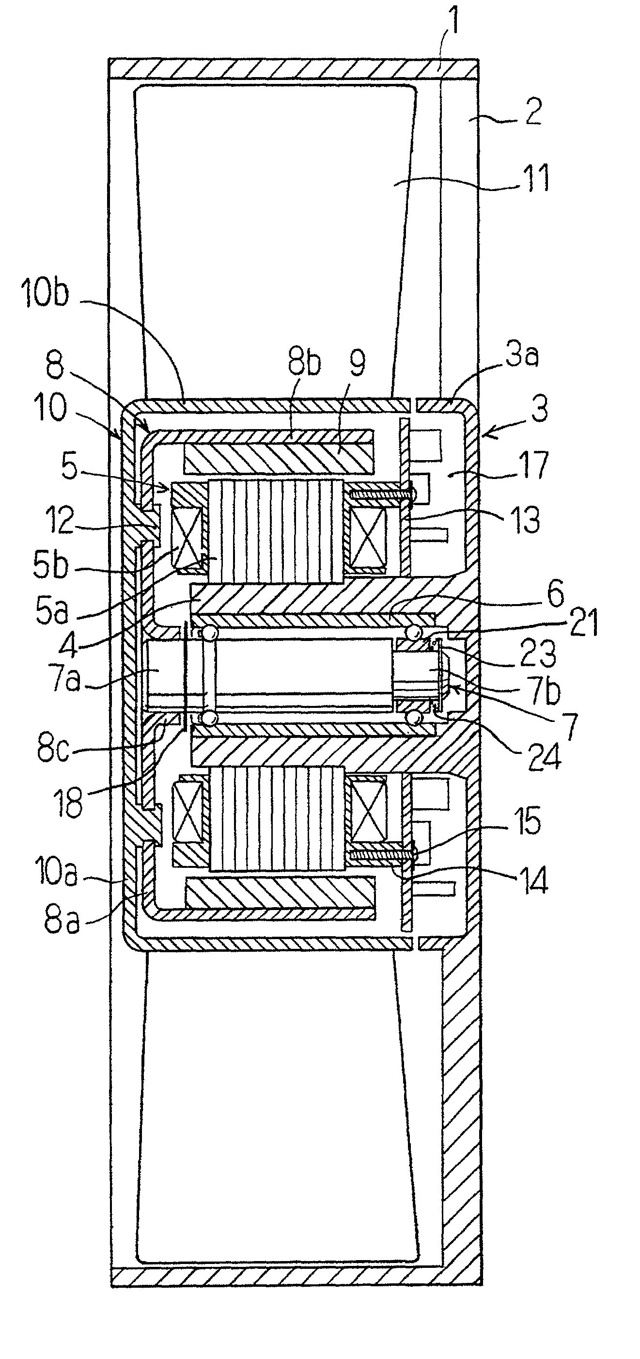
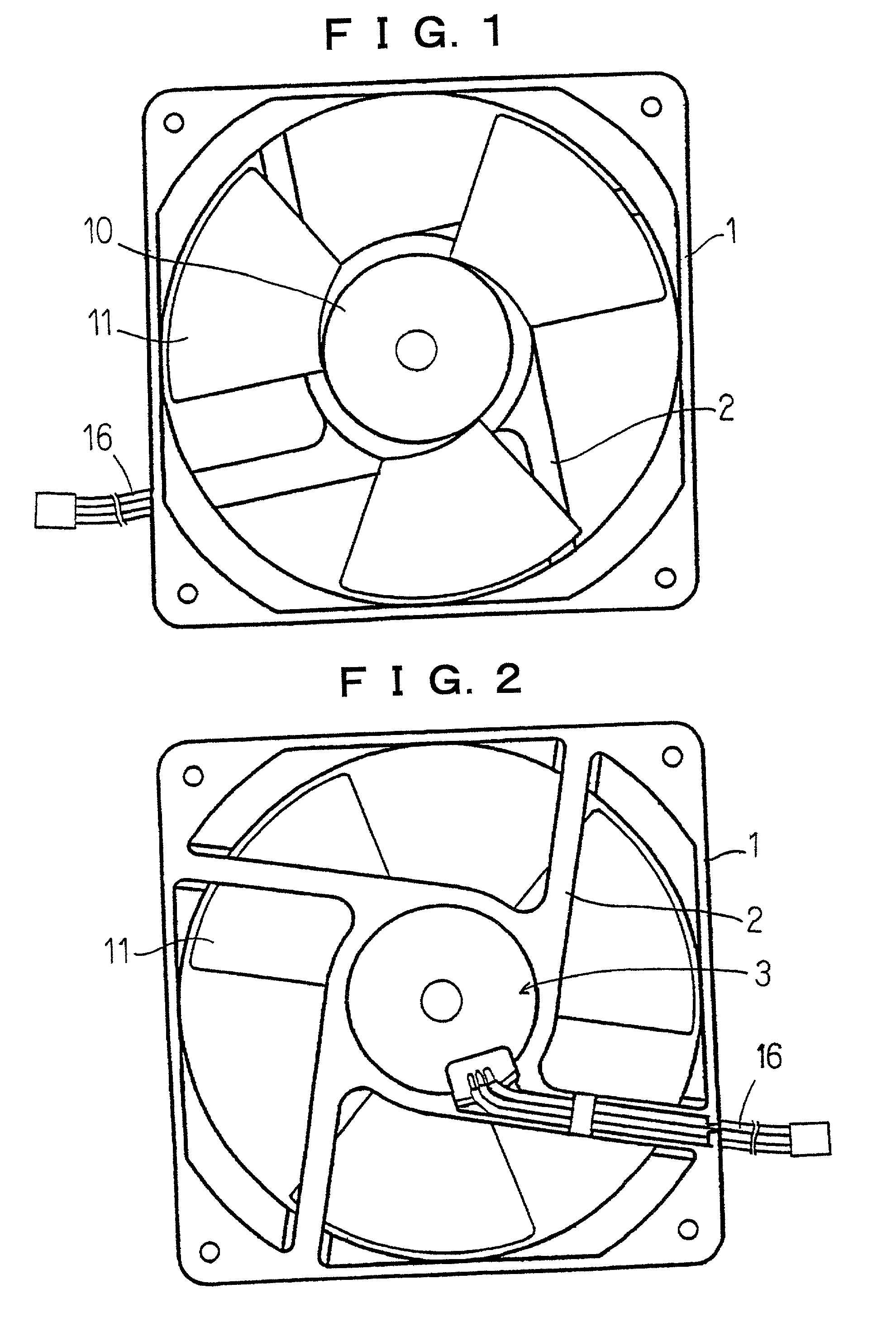
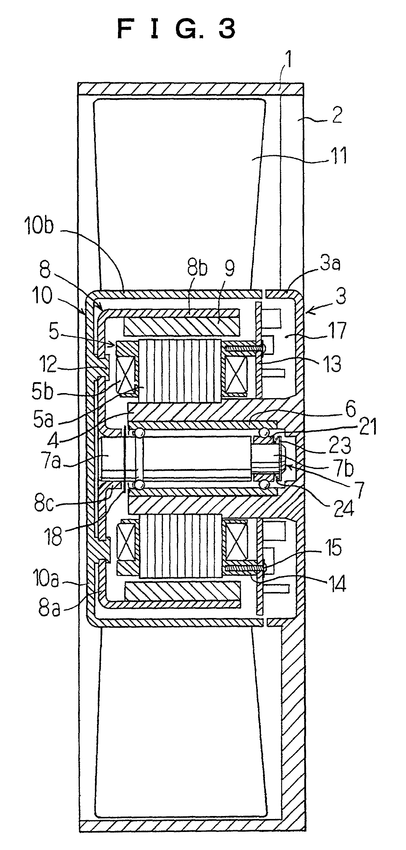
[0108] The blower in accordance with this embodiment is of a shaft rotating type. The frame of the body of the blower is designated by the reference numeral 1 in FIGS. 1-3. The frame is preferably made of synthetic resin.

[0109] A base 3 is supported through a few stays 2 by means of the frame formed integrally therewith. The outer periphery of the base 3 is formed with a flange 3a protruding frontward forming a relatively flat cylindrical configuration.

[0110] The base 3 also has a cylindrical bearing holder 4 protruding frontward formed integrally therewith. A stator 5 including an iron core 5a and coils 5b is provided around the exterior surface of the bearing holder 4. A sleeve 6 served as an outer ring of the bearing is secured by adhesive within the interior of the bearing holder 4.

[0111] A shaft 7 to be journalled through bearing means described hereinafter is disposed within the sleeve 6. At the distal end of the shaft protruding through the sleeve 6, a hub...

second embodiment

The Second Embodiment

[0130] The blower in accordance with this embodiment is a blower of a sleeve rotating type in which the shaft is stationary. The blower of this embodiment will now be described in detail with reference to FIG. 5.

[0131] The frame 1 is of substantially the same structure as that of the first embodiment and includes a base 3 positioned at the central portion of the frame. The base 3 has a cylindrical bearing holder 4 formed integrally therewith and extending frontward (i.e. leftward in FIG. 5) therefrom. A stator 5 including an iron core 5a and coils 5b is attached to the outer surface of the cylindrical bearing holder 4.

[0132] The bearing device including a sleeve 6, a shaft 7 and balls 20a, 20b interposed as double row therebetween is adapted to be inserted into the cylindrical bearing holder 4 in the reverse direction to that shown in FIG. 4. In this arrangement, the larger diameter portion 7a is inserted into a boss 26 of the base 3, and secured thereto by mean...

third embodiment

The Third Embodiment

[0137] The blower in accordance with this embodiment is also of the sleeve rotating type in which the shaft is stationary. The blower of this embodiment will now be described in detail with reference to FIG. 6.

[0138] The blower of this embodiment can be distinguished from those of the above mentioned embodiments in that the base 3 does not have the cylindrical bearing holder, the yoke is a cylindrical member, and the stator 5 is secured to the base.

[0139] The blower includes the stator attached to the inner peripheral surface of the flange 3a extending frontward from the base 3, and a magnet 9 connected to the annular yoke 8 fit around the exterior of the sleeve 6 of the bearing device of FIG. 4 and secured thereto. The outer periphery of the magnet 9 are spaced a distance from the inner peripheral surface of the stator 5.

[0140] The front end portion of the sleeve 6 is adapted to be inserted into the hub 27a for a central aperture provided through a supporting pl...


PUM


Abstract

The object of the present invention is to provide a blower including a bearing structure wherein the number of components is reduced, the cost for manufacturing can be reduced, and the diameter of the shaft can be increased. The bearing structure is good at its durability, eliminates or reduces the rotational run out, and provides superior quietness. The blower of the present invention having an impeller adapted to be rotated upon energizing the blower comprising; a bearing device for supporting a rotational center portion of the impeller, the bearing device including; a sleeve, a stepped shaft including a larger diameter portion and a reduced diameter portion provided at one end thereof, the first inner raceway groove formed at an appropriate position around the outer peripheral surface of the larger diameter portion, the first outer raceway groove formed on an inner peripheral surface of the sleeve so as to correspond with the first inner raceway groove, balls of the first row interposed between the first and second grooves, an inner ring slidably fit over the reduced diameter portion, the second inner raceway groove formed around an outer peripheral surface of the inner ring, the second outer raceway groove formed on the inner peripheral surface of the sleeve so as to correspond with the second inner raceway groove, balls of the second row interposed between the second inner and outer raceway grooves, a stop ring provided around the inner periphery of the distal end of the reduced diameter portion, and a pre-loading spring interposed between the stop ring and an end surface of the inner ring to provide a suitable amount of pre-loading force to the inner ring.

Description

[0001] 1. Technical Field[0002] The present invention relates especially to a blower suitable in the application for cooling office automation equipment.[0003] 2. Description of the Prior Art[0004] Conventionally, the double row bearing device emloyed in the blower for cooling the office automation equipment includes a pair of ball bearings 102 and 103 fit on a shaft 101 of the motor as shown in FIG. 8.[0005] Inner rings 102a, 103a of each ball bearing 102, 103 are loose fit to the shaft 101, and outer rings 102b, 103b are also loose fit within the sleeve 104 being the bearing housing.[0006] A compressed coil spring 106 for applying preload to both ball bearings is interposed between the outer surface of the inner ring 102a of the left ball bearing 102 disposed adjacent the yoke 105 and the front face plate 105a of the yoke 105 integrally connected to the front face plate 108a of the impeller 108. A stop ring 107 for retaining the ball bearing 103 is provided around the right end of...

Claims


Application Information

Patent Timeline
IPC IPC(8): F04D25/06F04D29/04F04D29/05F04D29/056F04D29/059F16C25/08
CPCF04D25/0606F04D29/0563F04D29/059
Inventor OBARA, RIKURO
Owner MINEBEA CO LTD
Why Eureka
Try Eureka