This helps you quickly interpret patents by identifying the three key elements:
Problems solved by technology
Method used
Benefits of technology
Benefits of technology
[0013] Another object of the present invention is to provide a printing apparatus and a printing method which can detect a printing position offset between printing heads in a main scanning direction on a printing medium and can set, if the detected offset amount is larger than a prescribed value, an in-block driving sequence independently for each printing head to correct the printing position offset.
[0016] In the apparatus and the method according to the present invention, a printing position offset between printing heads in a main scanning direction on a printing medium can be detected, and if the detected offset amount is larger than a prescribed value, an in-block driving sequence is set independently for each printing head to correct the printing position offset. Thereby, accuracy of printing position adjustment between printing heads in the main scanning direction can be increased, and then correcting a registration offset with accuracy can achieve a high quality image.
Problems solved by technology
The current serial scan type printing apparatuses mostly achieves such high definition of printing resolution with 360 dpi or more, that it has become difficult to reduce the registration offset with an improvement in the mechanical precision of scanning systems.
However, the former registration method has a considerable demerit in cost, since pulse generating means for generating drive pulses at an independent timing for each head and transfer means for transferring drive data at an independent timing, as well as timing controlling means for controlling short time intervals, must be provided with.
For example, when printing is performed with black ink on a printing medium having high color development characteristics, the printed portion becomes excessively black to reduce the absolute amount of reflected light, thereby causing the shortage of the output of the optical sensor.
For example, when printing is performed on an oozy printing medium such as plain paper, the adjacent dots are oozed to be merged with each other even if printing positions are varied, reducing a variation in density and making it difficult to select the optimum printing position.
However, when the printing registration pattern is printed with the ink having a high density and the ink having a low density, the relative difference in density of the printed portion between the heads becomes significant.
Namely, even if the relative printing position between the heads is varied, the result of printing with the high density ink becomes dominant to make it impossible to obtain density variations required for judgment of printing registration so as to cause difficulty in selecting the optimum printing position.
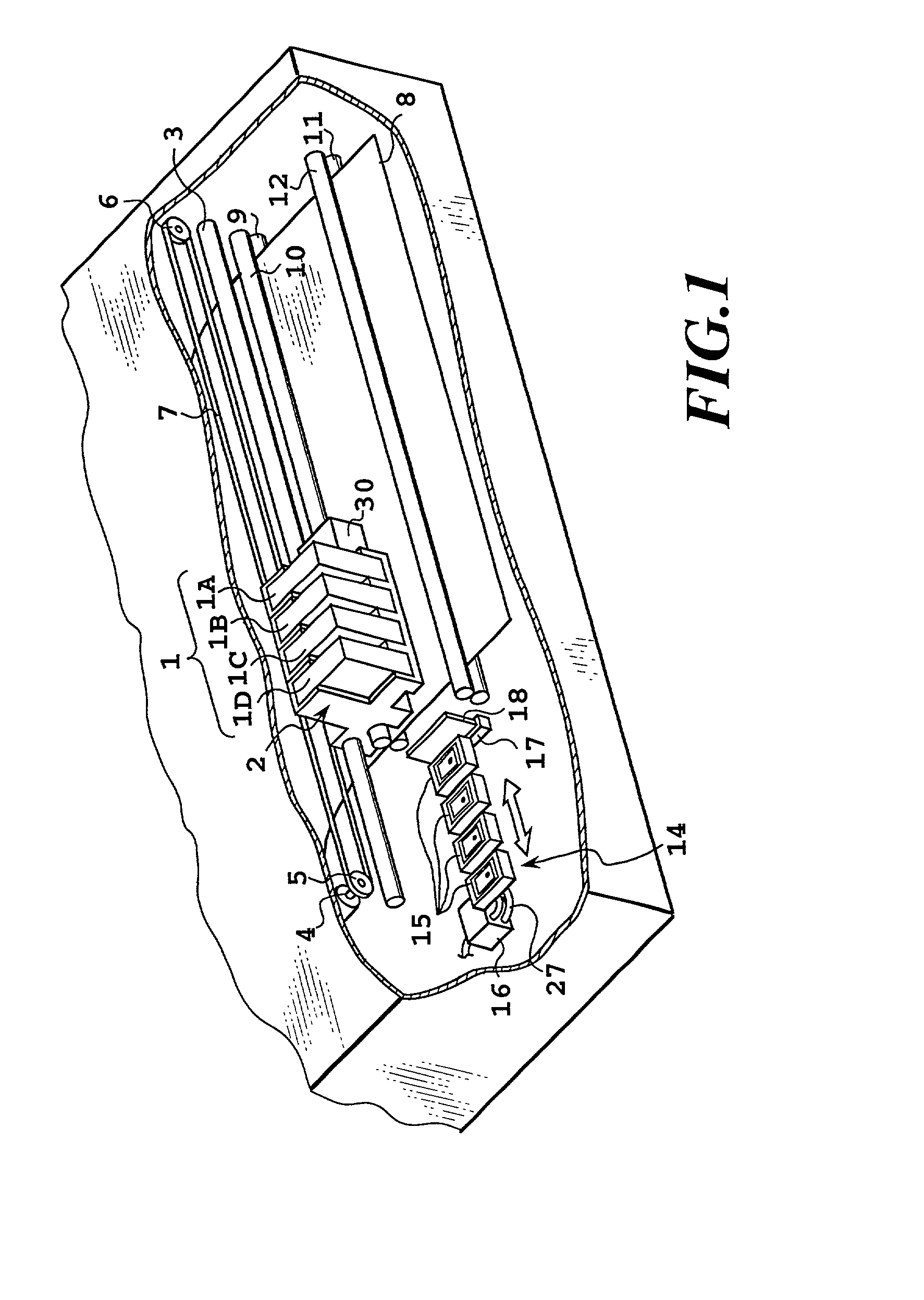
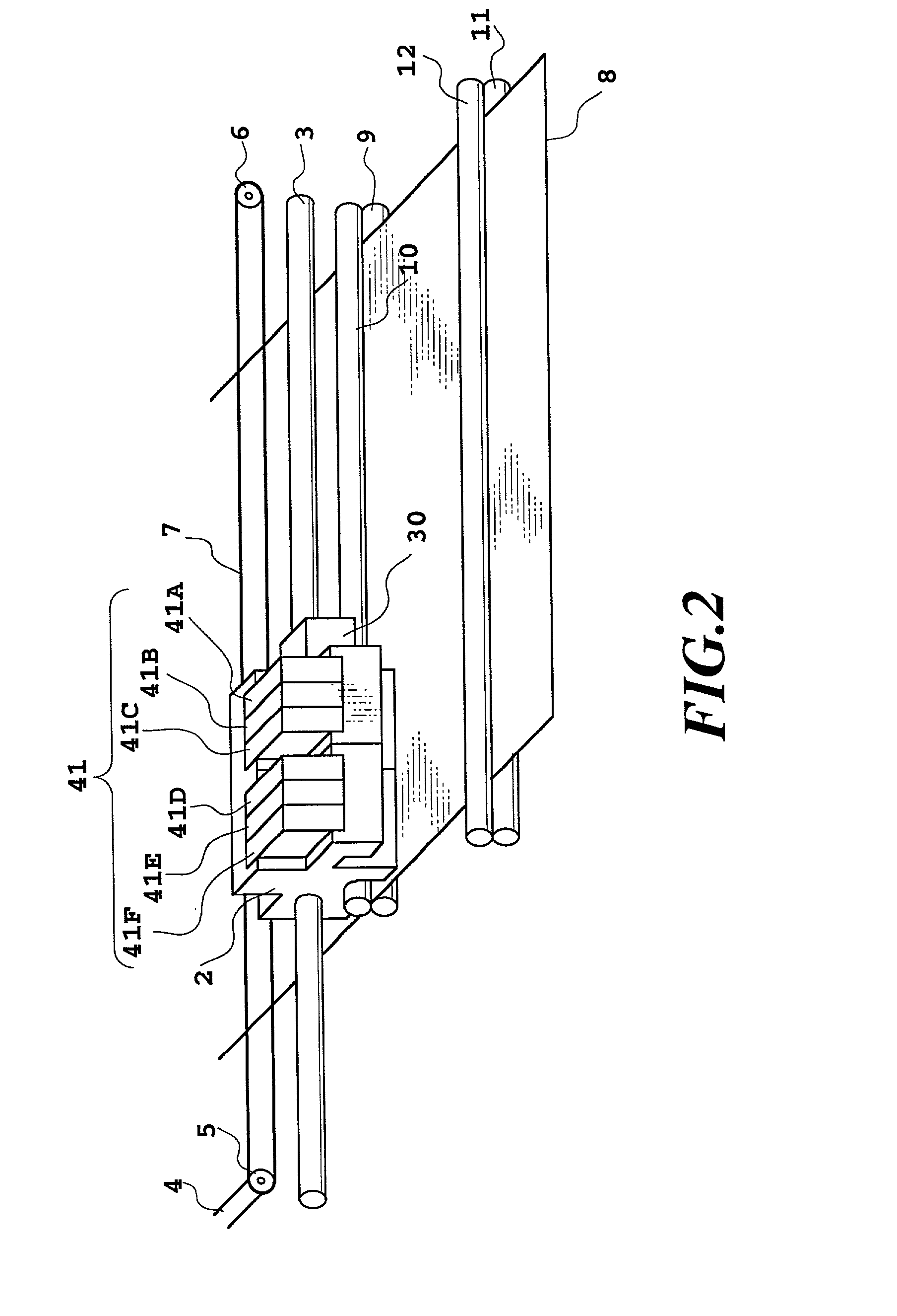
However, in the case where such pattern is printed on the printing medium 8 by the ink-jet printing apparatus, the printing medium 8 is expanded depending upon the kind of printing medium 8 if the ink is ejected to an area in excess of a predetermined amount, to possibly deteriorate the precision of deposition of the ink droplets ejected from the printing head.
Method used
Image
Click on the blue label to locate the original text in one second.
Reading with bidirectional positioning of images and text.
Examples
fifth embodiment
[0222] [Fifth Embodiment]
[0223] In a fifth embodiment, printing registration is performed between a plurality of heads in a carriage scanning direction.
[0225] Concerning the printing pattern explained in the fourth embodiment, dots printed in the forward scan is printed by a first head in the present embodiment, and the dots printed in the reverse scan is printed by a second head in the present embodiment, for performing printing registration. Judgment method of the printing registration condition is similar to that in the fourth embodiment.
[0227] Concerning a plurality of heads to be used, the pattern for making judgment of the optimum ink ejection duty is printed similarly to the fourth embodiment, for measuring the optical reflection index for respective patches. A linear region where the optical reflection index with respect to the ink ejection duty is linearly varied is deter...
sixth embodiment
[0231] [Sixth Embodiment]
[0232] In a sixth embodiment, printing registration is performed in a direction perpendicular to a carriage scanning direction between a plurality of heads.
[0234] In the present embodiment, there is used a printing pattern where the relationship between vertical and lateral directions is reversed in the printing pattern explained in the fifth embodiment. The judgment method of the printing registration condition is similar to that in the fourth embodiment.
[0236] In the same manner as in the fifth embodiment, concerning a plurality of heads to be used, the pattern for making judgment of the optimum ink ejection duty is printed similarly to the fifth embodiment, for measuring the optical reflection index for respective patches. A linear region where the optical reflection index with respect to the ink ejection duty is linearly varied is determined on the bas...
seventh embodiment
[0241] [Seventh Embodiment]
[0242] Seventh to tenth embodiments are suitable for performing printing using high density and low density inks in the printing apparatus shown in FIGS. 1 and 2.
[0243] Printing can be performed by using both of the high density ink and an ink diluted about three or four times with the high density ink (low density ink), or by using only the diluted ink (low density ink). In this case, the head must be frequently replaced for printing of an image primarily consisting of a text and for printing of an image primarily consisting of a graphic image, so that it becomes necessary to frequently perform printing registration.
[0244] However, when the user selects the condition where the printing positions are well registered by visual observation, the rules are printed on the printing medium with the high density ink and the low density ink. As a result, since the printing registration condition is determined by the user, it is possible to make it difficult to judg...
PUM
Abstract
With a printing apparatus and a head driving method according to the present invention, a plurality of printing heads having a plurality of recording elements and a printing medium are relatively moved in a prescribed direction, and the plurality of recording elements of each printing head are divided into a plurality of blocks and each element in each block are driven in a prescribed sequence during the relative movement. As a print position offset between the plurality of printing heads in the prescribed direction on the printing medium is detected and the detected amount is greater than a prescribed amount, on the basis of block sequence designater, an in-block driving sequence is set independently for the each printing head and on the basis of a sequence generated by block sequence generater, the each printing head is driven. Correcting the print position offset in this way produces accuracy of printing position adjustment between printing heads in the main scanning direction, and thereby correcting a registration offset with accuracy can achieve a high quality image.
Description
[0001] This application is based on Patent Application No. 10-092119 filed Apr. 3, 1998 in Japan, the content of which is incorporated hereinto by reference.[0002] 1. Field of the Invention[0003] The present invention relates to a printing apparatus and a head driving method thereof, and particularly relates to a printing apparatus of serial scan type having a plurality of printing heads, each having a plurality of in-line-arranged printing elements and a head driving method thereof.[0004] 2. Description of the Related Art[0005] Conventionally, a printing apparatus of a serial scan type is used, at an office or at home, for producing printouts of high quality color images. The serial scan type printing apparatus performs printing on a sheet-formed printing medium by a reciprocal printing head movement (henceforth referred to as main scanning), and carrying the printing medium by a prescribed amount per main scanning, in a direction substantially vertical to the reciprocal movement (...
Claims
Application Information
Patent Timeline
Application Date:The date an application was filed.
Publication Date:The date a patent or application was officially published.
First Publication Date:The earliest publication date of a patent with the same application number.
Issue Date:Publication date of the patent grant document.
PCT Entry Date:The Entry date of PCT National Phase.
Estimated Expiry Date:The statutory expiry date of a patent right according to the Patent Law, and it is the longest term of protection that the patent right can achieve without the termination of the patent right due to other reasons(Term extension factor has been taken into account ).
Invalid Date:Actual expiry date is based on effective date or publication date of legal transaction data of invalid patent.

