Test method of high-precision dynamic comparator and test circuit thereof

A technology of dynamic comparator and test method, which is applied in the direction of measuring electrical variables, measuring current/voltage, instruments, etc., can solve problems such as time-consuming and energy-consuming, and achieve simple and fast results

Inactive Publication Date: 2012-05-02
FUZHOU UNIV
View PDF4 Cites 10 Cited by
  • Summary
  • Abstract
  • Description
  • Claims
  • Application Information

AI Technical Summary

Problems solved by technology

[0004] This traditional method of measuring the input offset voltage of a comparator is very time-consuming and labor-intensive

Method used


Image

  • Test method of high-precision dynamic comparator and test circuit thereof
  • Test method of high-precision dynamic comparator and test circuit thereof
  • Test method of high-precision dynamic comparator and test circuit thereof

Examples


Embodiment Construction

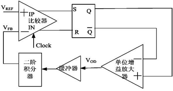
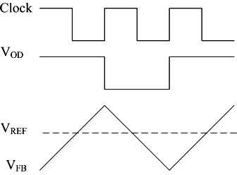
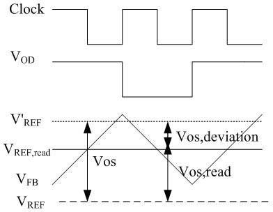
[0014] The present embodiment provides a method for testing a high-precision dynamic comparator. The method first judges the output state of the comparator through a clocked SR latch, and inputs the judged output signal into a unity-gain amplifier; secondly, provides a The second-order integrator provides a feedback voltage for the comparator after positive and negative integration of the output signal of the unit gain amplifier through the buffer. .

[0015] In order to realize the above-mentioned method, the present embodiment provides a test circuit of a high-precision dynamic comparator, which is characterized in that, comprising: a comparator; a clocked SR latch; its input terminal is connected to the output terminal of the comparator; a unity gain amplifier having an input connected to the output of the clocked SR latch; and a second order integrator having an input connected to the output of the buffer and an output providing a feedback for the comparator Voltage . ...


PUM


Abstract

The invention relates to a test method of a high-precision dynamic comparator. The method is characterized by: firstly, through a clock control SR latch, determining an output state of the comparator and inputting a determined output signal into a unity gain amplifier; secondly, providing a second order integrator and providing a feedback voltage for the comparator after positive integration or backward integration is performed to positive and negative of the signal which passes through a buffer and is output by the unity gain amplifier. Besides, the invention provides a test circuit which can realize the above method. In the invention, through one simulation to the dynamic comparator, an input offset voltage can be obtained. Test precision can be controlled by human beings. Rapidity and accurate adjustability of the test can be realized.

Description

technical field [0001] The invention relates to a testing method and testing circuit of a high-precision dynamic comparator. Background technique [0002] Dynamic comparators are widely used in analog-to-digital converters, data acquisition systems, etc. Among them, dynamic comparators with low input offset voltage and high precision are developing rapidly, but the corresponding simulation methods still have great limitations. The traditional simulation method is: the open-loop comparator of the operational amplifier structure can obtain the input offset voltage through DC scanning, that is, input a reference signal at one input terminal of the open-loop comparator, input a DC signal at the other end, set it as a variable, and then Carry out parameter scanning, and the difference between the turning point voltage and the reference signal voltage when the output result jumps is the offset voltage. [0003] Because the comparator cannot do DC sweep. Therefore, different sign...

Claims


Application Information

Patent Timeline
Patent Type & Authority Applications(China)
IPC IPC(8): G01R19/00
Inventor 胡炜何明华王法翔张志晓
Owner FUZHOU UNIV
Why Eureka
Try Eureka