

Image forming apparatus
a technology of image data and forming apparatus, which is applied in the direction of digital output to print units, digitally marking record carriers, instruments, etc., can solve the problems of image data missing timing when being printed on paper, four colors, ymck,
- Summary
- Abstract
- Description
- Claims
- Application Information
AI Technical Summary
Benefits of technology
Problems solved by technology
Method used
Image

Examples
first embodiment
[0118] The outline of a first embodiment will now be described.
[0119] According to the first embodiment, in the event that it takes a long time to read image data from the storage device, such as a hard disk drive (HDD), to the page buffer due to read error, in order to certainly assure that storage of image data of the four colors (YMCK) is present in the page buffers 153a through 153d at the timing at which paper is to be fed without increasing the capacity of the page buffer in vain, at first, feeding paper does not start till image data of all colors of a page to be printed are stored in the page buffers 153a through 153d. Secondary, the page buffers 153a through 153d have memory capacity capable of storing image data corresponding to the amount of a gap among drums.
[0120] Hereinafter, the first embodiment will be described in detail by giving a specific example.
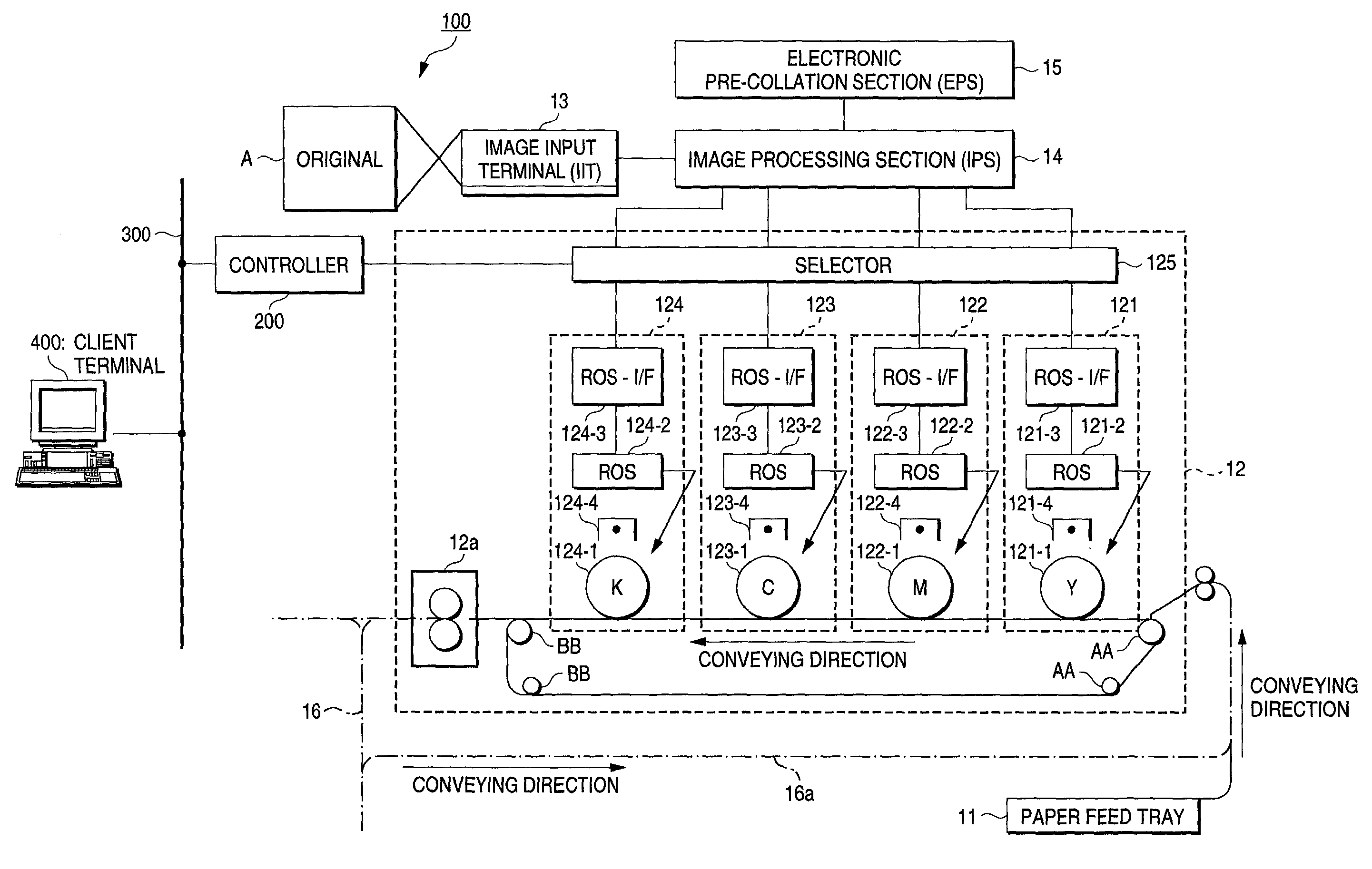
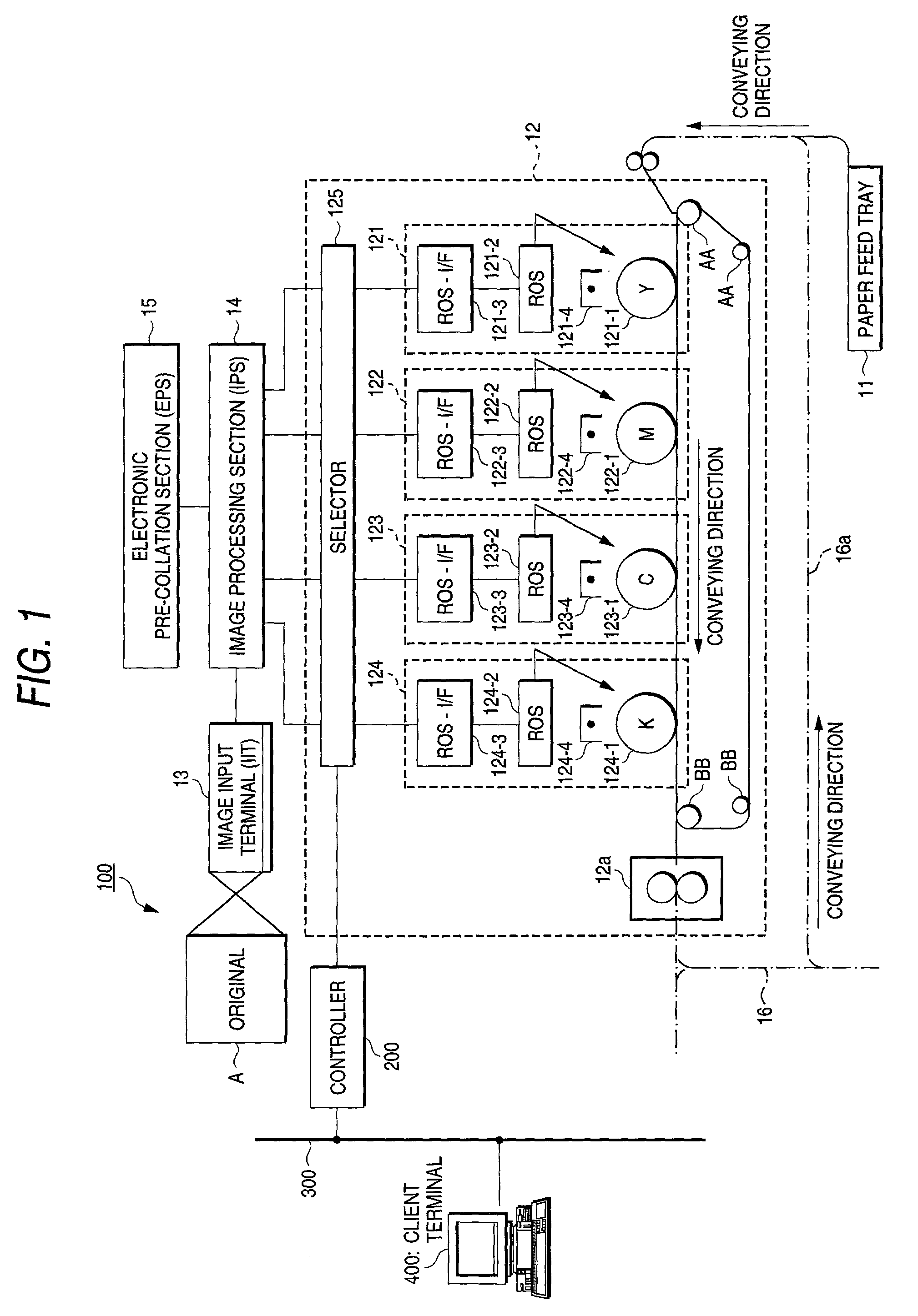
[0121] FIG. 6 shows an example of configuration of the page buffers 153a through 153d of the EPCs 15a through 15d of Y...
second embodiment
[0160] There will now be described a
[0161] With reference to flowcharts shown in FIGS. 13 and 14, there will be described a processing operation according to the present invention in case that output from the IOT is controlled in accordance with state of storage of image data in the page buffers.
[0162] FIG. 13 is a flowchart showing processing procedures to be performed at a time of reading of image data (i.e., a copy scan operation).
[0163] As shown in FIG. 13, reading image data is performed at the IIT 13 (step S101).
[0164] Subsequently, compression of the read image data is performed at the EPC 15 (step S102). Here, a specific compression ratio is 1 / 5.33.
[0165] Next, the thus-compressed image data are transferred to (written into) the page buffers 153a through 153d (step S103). A determination is made as to whether or not image data of one page have been written (step S104). When the result of the determination shows that the image data of one page have finished being written (ste...
third embodiment
[0180] A third embodiment will now be described.
[0181] Process operation procedure to be performed in case that feeding of paper is controlled in accordance with a storage state of image data in the page buffers will now be described with reference to a flowchart shown in FIG. 15.
[0182] FIG. 15 is a flowchart showing process procedure to be performed in case that feeding of paper is controlled in accordance with the storage state of image data in the page buffers.
[0183] As shown in FIG. 15, when a copy print job is started, image data is first read from an HDD (step S301), and the image data is written into the page buffer (step S302).
[0184] A determination is made as to whether or not an output timing is acceptable (step S303).
[0185] If the result of the determination shows that preparation of the output timing is acceptable (step S303 YES), a determination is made as to whether or not image data of predetermined level 1 (e.g., about 70% of the page buffer) or more is stored in the...
PUM
 Abstract
Description
Claims
Application Information