Image processing apparatus, image processing method and portable imaging apparatus

Inactive Publication Date: 2007-01-30
SHARP KK
View PDF13 Cites 10 Cited by
  • Summary
  • Abstract
  • Description
  • Claims
  • Application Information

AI Technical Summary

Benefits of technology

[0036]The thus-constructed image processing apparatus of the present invention minimizes the capacity of buffers, resulting in miniaturization of the apparatus. Therefore, the present invention is suitably applied to digital data capturing, separation and conversion between luminance data and color difference data, JPEG compression processing, conversion to video signals, filtering, etc., which are performed in a portable imaging apparatus using

Problems solved by technology

In such image processing, a vast amount of data needs to be processed.
However, if the buffer capacity is limited, the maximum line width of an image region which can be processed

Method used


Image

  • Image processing apparatus, image processing method and portable imaging apparatus
  • Image processing apparatus, image processing method and portable imaging apparatus
  • Image processing apparatus, image processing method and portable imaging apparatus

Examples


example 1

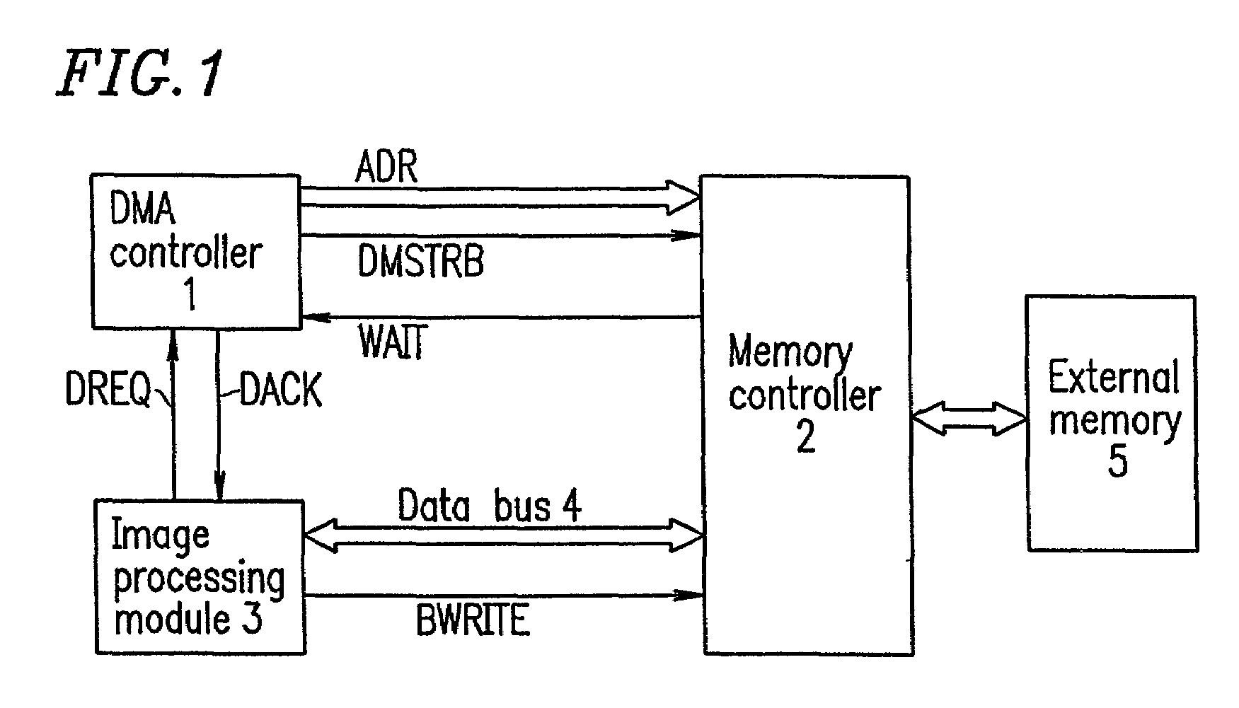
[0053]FIG. 1. is a block diagram showing a configuration of an image processing apparatus according to Example 1 of the present invention. This image processing apparatus comprises a DMA controller 1, a memory controller 2, an image processing module 3 and an external memory 5, among which image data is transferred via a data bus 4. For the sake of simplification, the control of the DMA controller 1 is described without reference to a CPU (not shown). Further, it is assumed that there is only one image processing module 3. In FIG. 1, a configuration for subjecting image data from a charge coupled device (CCD) to analog-to-digital conversion and inputting the resultant data into the image processing module 3, and after conversion of the resultant data into a video signal, a configuration for outputting the video signal to a display, are omitted.

[0054]In the image processing apparatus, the image processing module 3 comprises an input buffer and an output buffer so that image data is i...

example 2

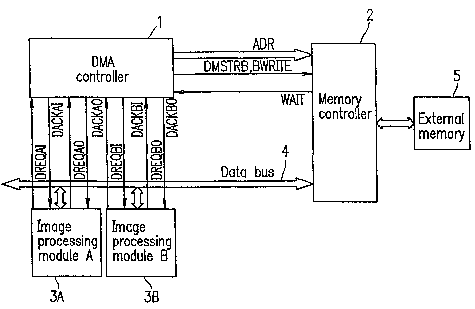
[0099]FIG. 5 is a diagram for explaining an image processing apparatus according to Example 2 of the present invention. In Example 2, two image processing modules share a data bus.

[0100]In Example 2, the DMA controller 1 is assigned separate DMA channels so as to control input and output of data to and from image processing modules 3A and 3B. In FIG. 5, signals input from the image processing module 3A are designated by their signal names with a suffix AI, and signals output therefrom are designated by their names with a suffix AO. Further, signals input from the image processing module 3B are designated by a suffix BI and signals output therefrom are designated by their names with a suffix BO. Channels are distinguished from one another by designating the names with suffixes, AI, AO, BI, and BO including the names A and B of the modules and the I and O of the terms input and output of the modules.

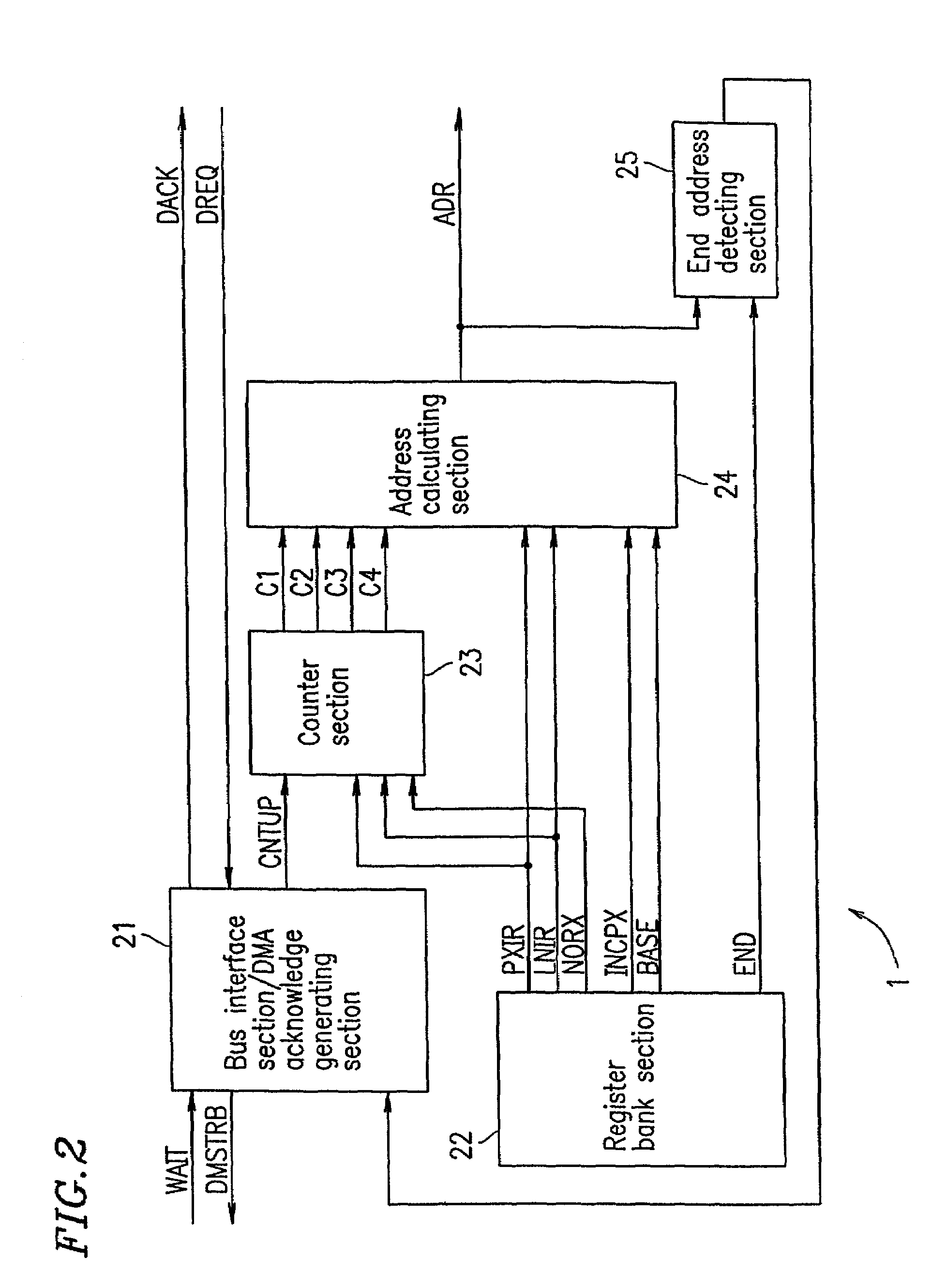
[0101]FIG. 6 is a diagram for explaining a configuration of a DMA controller of Exampl...

example 3

[0106]In Example 3, a case where the same data needs to be repeatedly transferred will be described.

[0107]For example, local image data processing carried out in an image processing module may be smoothing in which the output data of a pixel is calculated by referencing a plurality of neighboring pixels. In this case, when data is transferred on a block-by-block basis, the pixel data of a peripheral portion of a block to be transferred needs to be repeatedly transferred in order to match and superpose the block with its adjacent block(s).

[0108]To address such a situation, in Example 3, in addition to the elements in Examples 1 and 2, the register bank section 22 of the DMA controller 1 comprises an additional register which stores the number of pixels YINC in a vertical line from the uppermost line of a block to the uppermost line of another block immediately below that block from which data transfer is initiated again after the image data of all of the blocks in one horizontal stag...


PUM


Abstract

An apparatus for processing an image includes a memory for storing the image data of each pixel in the plurality of unit blocks, a direct memory access controller for reading the image data from the memory by accessing the memory on a block-by-block basis by generating the addresses of the pixels in each unit block, and a plurality of image processing modules for receiving the image data of each unit block read based on the addresses generated by the direct memory access controller and sequentially transferred via a data bus, processing the image data of the unit block, and outputting the processed image data of the unit block.

Description

BACKGROUND OF THE INVENTION[0001]1. Field of the Invention[0002]The present invention relates to an image processing apparatus and an image processing method, and a portable imaging apparatus using the same, such as a digital still camera, etc. More particularly, the present invention relates to an image processing apparatus and an image processing method in which image data is processed by repetition of data transfer between an image processing module which subjects local image data to a predetermined image processing, and a large-scale memory capable of storing data an entire image data, by means of direct memory access (hereinafter referred to as DMA) but not via a CPU, and to a portable imaging apparatus including the same.[0003]2. Description of the Related Art[0004]An exemplary digital still camera works in the following manner. Image data is captured by a charge coupled device (CCD) through a color filter. The captured image data is split and converted from RGB data on a Baye...

Claims


Application Information

Patent Timeline
IPC IPC(8): H04N5/228G06F13/28G06T1/60H04N5/225H04N101/00
CPCG06T1/60
Inventor MATSUKI, HIROYUKITAKAI, KENSUKE
Owner SHARP KK
Why Eureka
Try Eureka