Apparatus and method for determining spatial orientation

a technology of spatial orientation and applicability, applied in the field of applicability and method for determining spatial orientation, can solve the problems of increasing the cost and efficiency of solutions derived, not revealing calculating misalignment, and relatively complicated digital pen applications. the effect of reducing the number of electrical components

Inactive Publication Date: 2002-04-25
ANOTO AB
View PDF0 Cites 89 Cited by
  • Summary
  • Abstract
  • Description
  • Claims
  • Application Information

AI Technical Summary

Benefits of technology

0009] Systems and methods consistent with the present invention may reduce the number of electrical components necessary to determine spatial relationship between a surface and a de

Problems solved by technology

According to the known art, digitized pen applications may be relatively complicated electrical arrangements in the pointing device and a base intended specifically for the pointing device.
The arrangements and the method disclosed in U.S. Pat. No. 5,198,623 include a large

Method used


Image

  • Apparatus and method for determining spatial orientation
  • Apparatus and method for determining spatial orientation
  • Apparatus and method for determining spatial orientation

Examples


Embodiment Construction

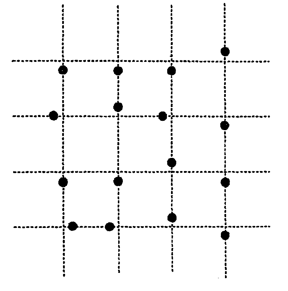
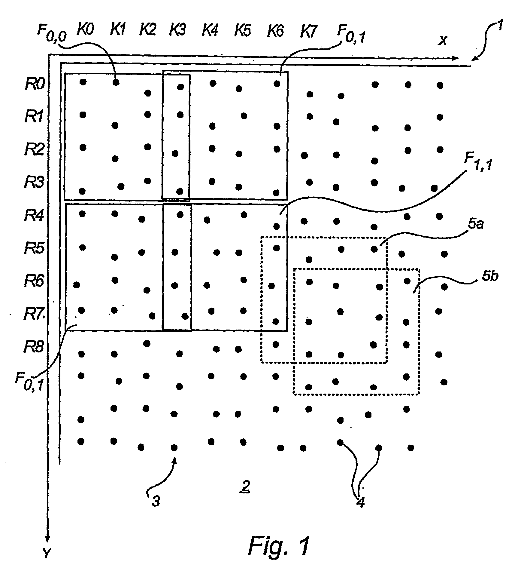
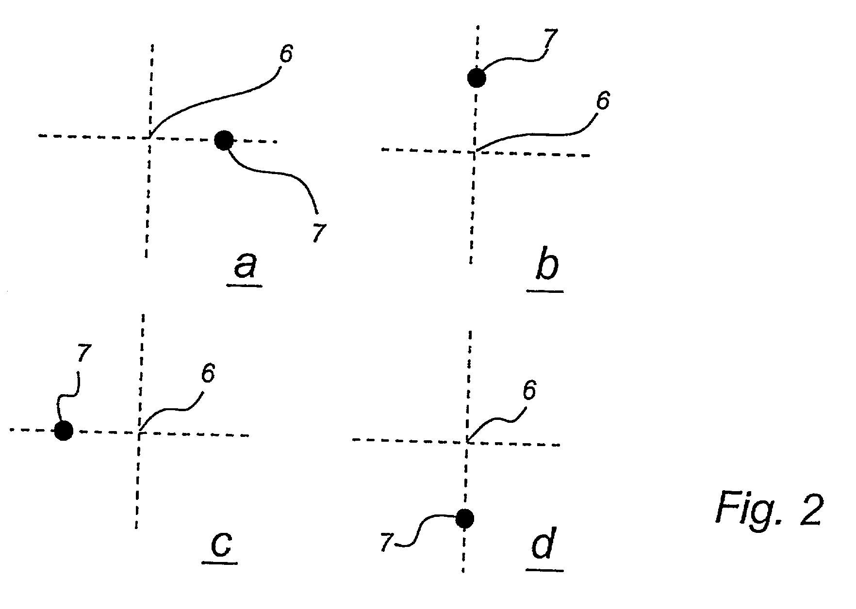
[0028] For the sake of clarity, the detailed description below of the invention has been divided into a number of part descriptions. By way of introduction, a coding pattern may be described with reference to FIGS. 1, 2a-d, and 3. As outlined above, this coding pattern may represent positional information, but can also represent other information. After the description of the coding pattern, an example of apparatus that may read the pattern is then described with reference to FIG. 4. The way a pattern can be used for calculating spatial orientation of an apparatus reading the pattern is then described with reference to FIGS. 5 and 6.

[0029] Although only one example of a coding pattern will be used in illustrating the invention, it is possible to make use of any other suitable coding pattern. Examples of such patterns are to be found in U.S. Pat. Nos. 5,852,434, 5,051,736, EP-A-0 469 864 (Xerox) as well as assignee's own disclosure WO 00 / 73983, which is hereby incorporated by referen...


PUM


Abstract

A system and a corresponding method for determining a spatial relationship between a surface having a predetermined pattern and an apparatus are disclosed. A portion of the surface may be imaged and compared with the predetermined pattern. The comparison produces at least one reference measurement that may be used to determine a spatial relationship expressed in at least parameters that define an orientation of the surface. By using knowledge of the predetermined pattern together with an algebraic model of the image formation by the apparatus, a numerical adaptation can be performed. Parameters obtained from the adaptation can then be used to calculate the spatial relationship between the apparatus and the surface in terms of, for example, a distance between the apparatus and the surface or an angle between the surface and an axis extending through the apparatus.

Description

[0001] This application claims priority benefits based on Swedish Patent Application No. 0000951-4, filed Mar. 21, 2000, and U.S. Provisional Application 60 / 207,844, filed May 30, 2000, the technical disclosures of each are hereby incorporated herein by reference.[0002] The present invention relates to pattern recognition and detection. Specifically, the present invention relates to methods and apparatuses for determining a spatial relationship between an input apparatus and a surface.[0003] To input information into computerized equipment, a pointing device, such as a computer mouse, or digitizing pen may be used. A feature common to these types of devices is that in most cases they supply only information directly related to two spatial dimensions.[0004] A typical computer mouse, for example, moves on top of a plane surface, and coded information about the movement of the mouse is supplied to a computer via mechanical rolling arrangements, electro-mechanical circuits and coding lo...

Claims


Application Information

Patent Timeline
IPC IPC(8): G06F3/03G06F3/033
CPCG06F3/03545G06F3/0317G06F3/0321
Inventor FAHRAEUS, CHRISTERBURSTROM, STEFANPERSSON, ERIKPETTERSSON, MATS PETTER
Owner ANOTO AB
Why Eureka
Try Eureka