Hand-held epilating device

a technology of epilating device and hand, which is applied in the field of hand-held epilating device, can solve the problems of difficulty in assembling the increased number of springs into the rotary cylinder, and it is not practical to provide a large number of pinching rows

Inactive Publication Date: 2002-05-02
MATSUSHITA ELECTRIC WORKS LTD
View PDF1 Cites 29 Cited by
  • Summary
  • Abstract
  • Description
  • Claims
  • Application Information

AI Technical Summary

Benefits of technology

[0006] It is therefore a primary object of the present invention to provide the epilating device which is capable of achieving efficient hair plucking due to the increased number of the pinching row units around the rotary cylinder, yet ensuring to moving the movable blades away from the adjacent stationary blades by the use of the return spring for successfully catching the hairs with increased hair trapping efficiency.
[0007] In a preferred embodiment, the return spring includes a plurality of spring arms extending radially from a center hub secured to the rotary cylinder. Each spring arm is held in pressing engagement simultaneously with the circumferentially adjacent actuator bars for urging the bars axially outwardly of the rotary cylinder. Thus, the number of the spring arms can be half that of the circumferentially arranged pinching units, thereby simplifying the structure of the return spring.

Problems solved by technology

Consequently, as the number of the pinching rows increases, a correspondingly increased number of the springs have to be incorporated in the rotary cylinder, which incurs difficulty of assembling the increased number of the springs into the rotary cylinder.
Therefore, it has not been practical to provide a large number of the pinching rows yet using the return springs for each of the pinching rows.

Method used


Image

  • Hand-held epilating device
  • Hand-held epilating device
  • Hand-held epilating device

Examples


Embodiment Construction

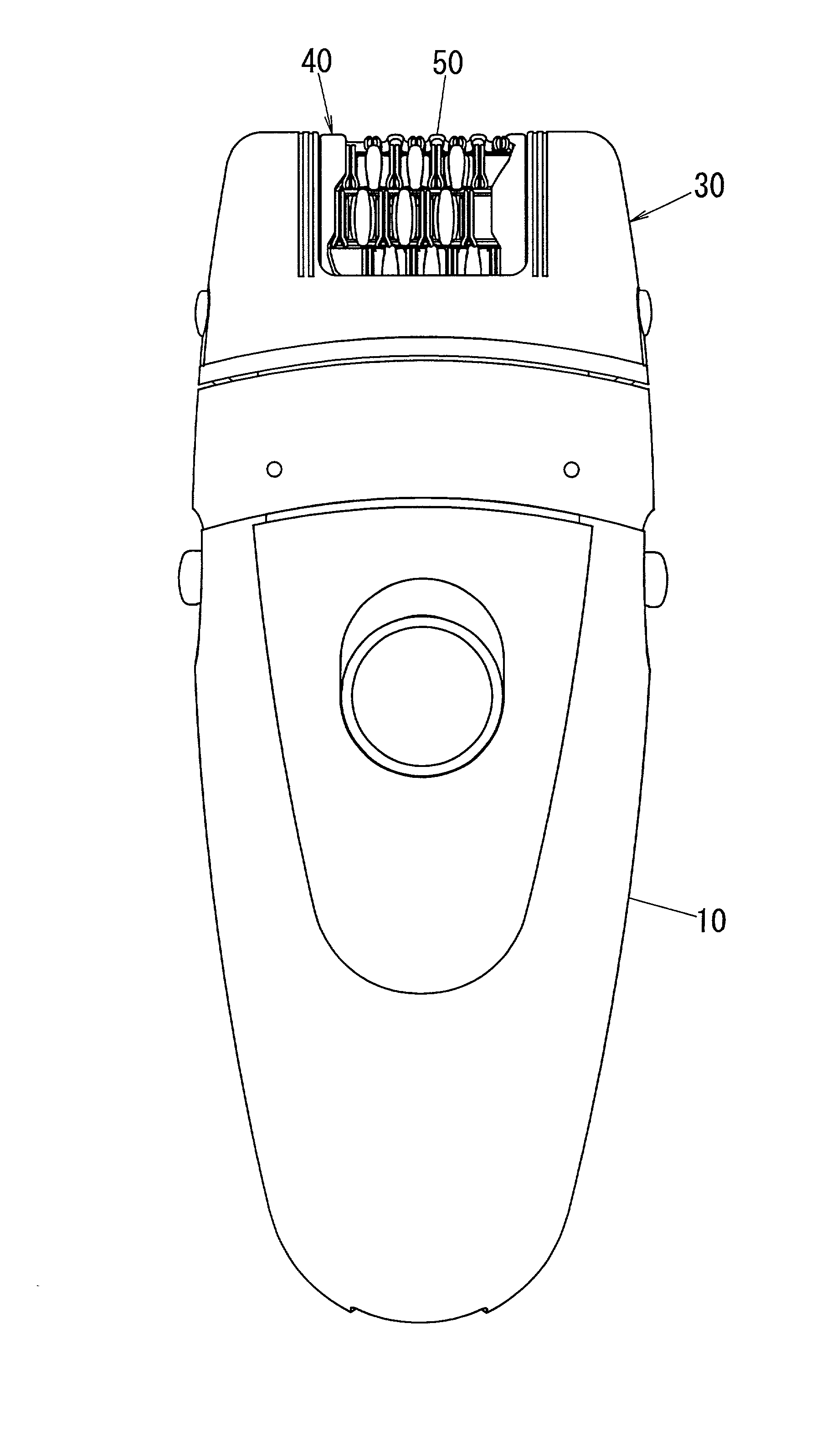
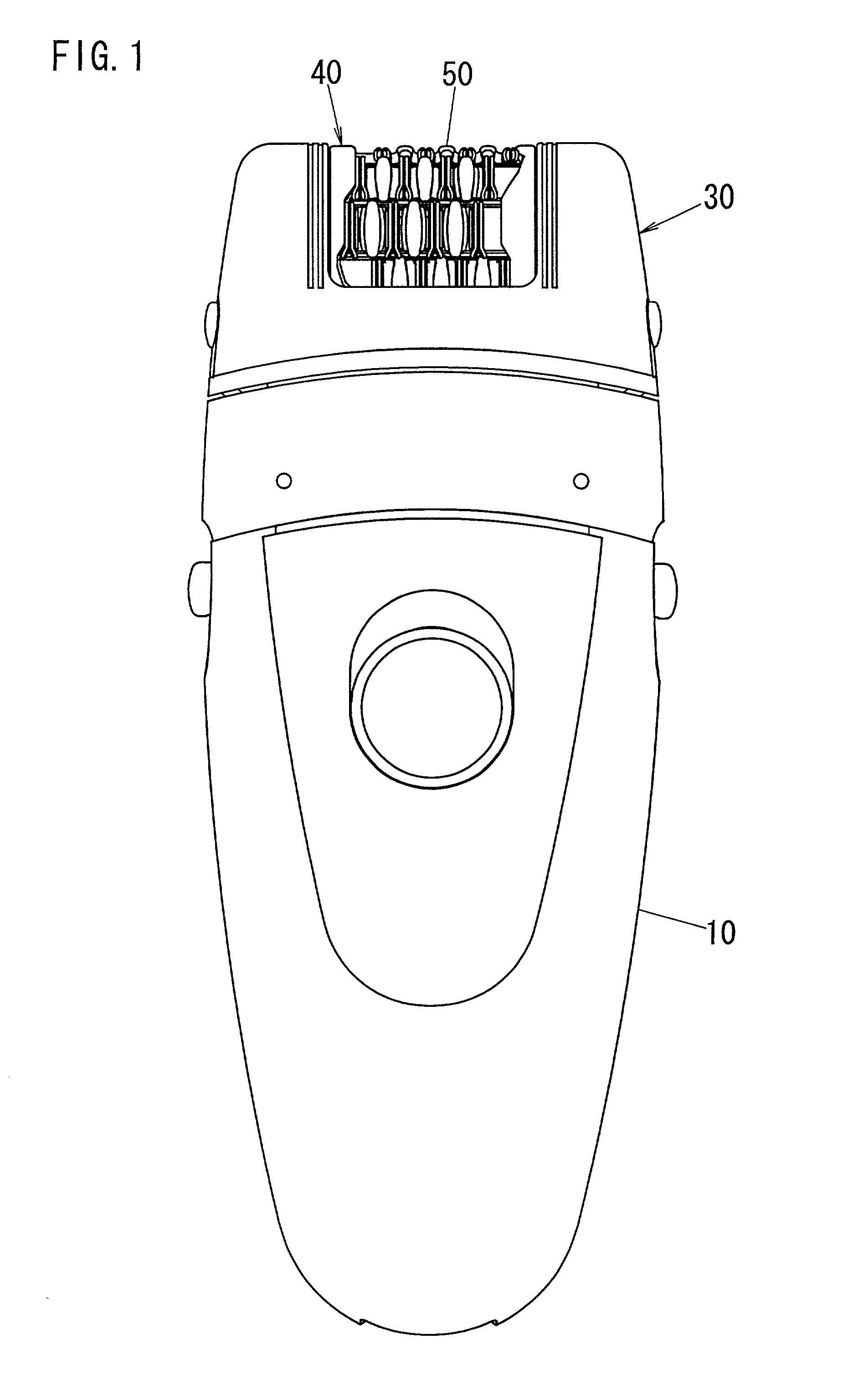
[0036] Referring now to FIG. 1, there is shown a hand-held epilating device in accordance with a preferred embodiment of the present invention. The epilating device has a housing 10 to be grasped by a user's hand and an epilator head 30 detachably mounted on top of the housing 10. The epilator head 30 carries a rotary cylinder 40 which is driven to rotate about its longitudinal axis for plucking body hairs from the skin of a user. The housing 10 accommodates an electric motor and a set of driving gears for providing a driving source of rotating the rotary cylinder 40 and simultaneously vibrating the cylinder along the longitudinal axis for maximizing for maximizing the chance of plucking the hairs on the surface of the rotary cylinder 40.

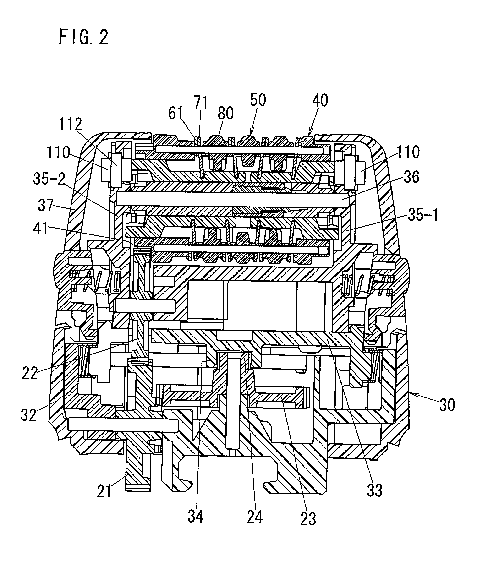
[0037] As shown in FIGS. 2 and 3, the epilator head 30 is composed of a base 31 detachably mounted to the housing 10, a base cover 32, a reciprocating platform 33, a head frame 35 supporting a rotary cylinder 40, and a head cover 38. The base 31 car...


PUM


Abstract

An epilating device has a rotary cylinder carrying a plurality of pinching row units arranged around the cylinder. An actuator bar is connected to movable blades in each row unit and is caused by a driven mechanism to move the movable blades towards the adjacent blades for pinching body hairs therebetween and plucking the hairs as the cylinder rotates. After the actuator bar is released from the driven mechanism, the bar is urged by a return spring to move the blades away from the adjacent blade to be ready for subsequent hair pinching. All the actuator bars spaced circumferentially around the cylinder and provided respectively for the row units are coupled commonly to the one return spring so that the epilating device can have an increased number of the row units around the cylinder only at a minimum number of the springs.

Description

[0001] 1. Field of the Invention[0002] The present invention is directed to a hand-held epilating device, and more particularly to such a device having a rotary cylinder carrying a plurality of hair pinching rows arranged around an axis of the rotary cylinder.[0003] 2. Description of the Prior Art[0004] U.S. Pat. No. 5,190,559 discloses a prior art epilating device which has a rotary cylinder carrying a pair of hair pinching rows spaced circumferentially around the rotary cylinder. Each of the pinching rows includes a plurality of stationary blades and a plurality of movable blades which are arranged along the lengthwise direction of the rotary cylinder with the tow adjacent movable blades disposed on opposites of each stationary blade. The movable blades in each pinching row are supported to a pair of actuator bars which are driven to counter-reciprocate along the longitudinal axis of the rotary cylinder in order to shift the movable blades towards the adjacent stationary blades fo...

Claims


Application Information

Patent Timeline
Patent Type & Authority Applications(United States)
IPC IPC(8): A45D26/00
CPCA45D2026/0085A45D26/0028A45D26/00
Inventor INOUE, TOMOYUKISUEYOSHI, HIDEKAZUIWASAKI, JYUZAEMONYANAGI, KOTARO
Owner MATSUSHITA ELECTRIC WORKS LTD
Why Eureka
Try Eureka