Label switching router

a label switching router and label technology, applied in the field of label switching routers, can solve the problems of increasing the load of the server, the inability to perform real-time operations, and the inability to perform single-unidirectional lsp

Inactive Publication Date: 2002-05-16
FUJITSU LTD
View PDF4 Cites 38 Cited by
  • Summary
  • Abstract
  • Description
  • Claims
  • Application Information

AI Technical Summary

Problems solved by technology

However, in the prior art MPLS, only a single unidirectional LSP can be set with a single operation.
(1) In case the LSP setup operation is performed at the two LSR's which assume the entrances, it is necessary to perform an up direction LSP setup and a down direction LSP setup respectively. Since it takes time to establish a bidirectional LSP, a real-time operation can not be performed.
(2) In case the external database server is used, a database amount swells in proportion to the network scale, so that a memory amount and the load of the server increase. Since it is required that in

Method used


Image

  • Label switching router
  • Label switching router
  • Label switching router

Examples


embodiment (

[0197] Embodiment (6)

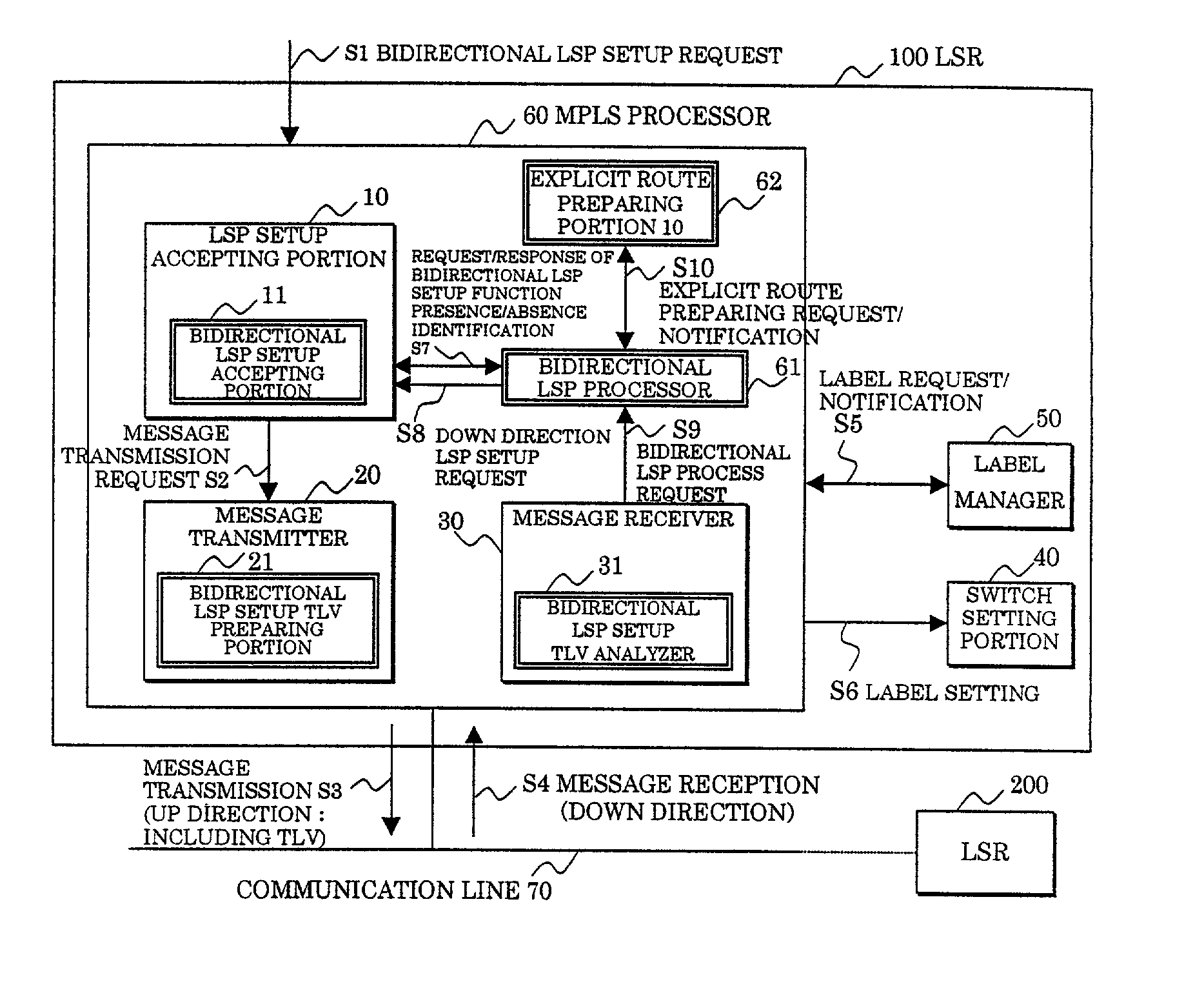
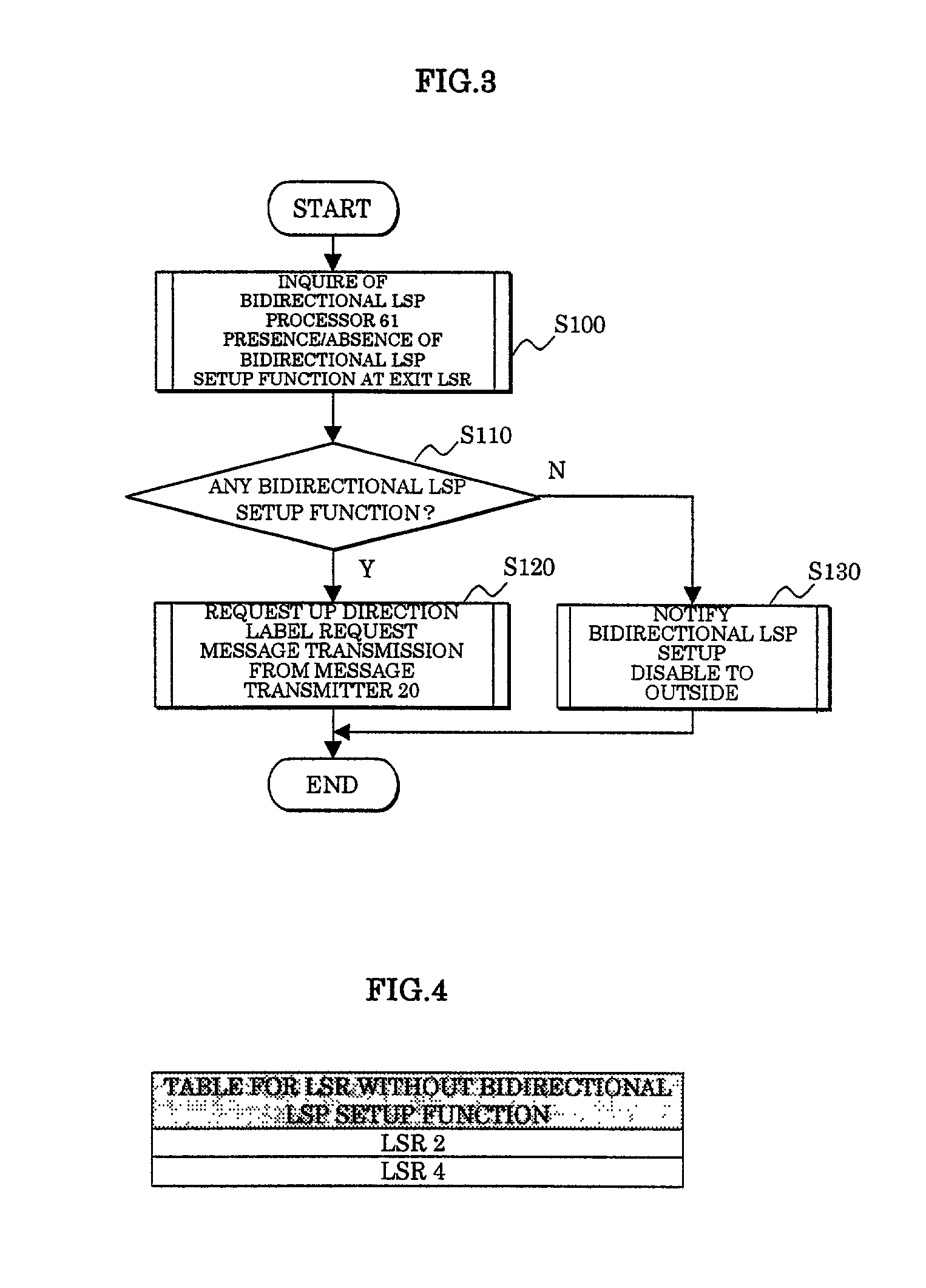
[0198] Embodiment (6) is one for storing the presence / absence of the bidirectional LSP setup function of the exit LSR at the entrance LSR, thereby avoiding the repetition of the failure of the bidirectional LSP setup.

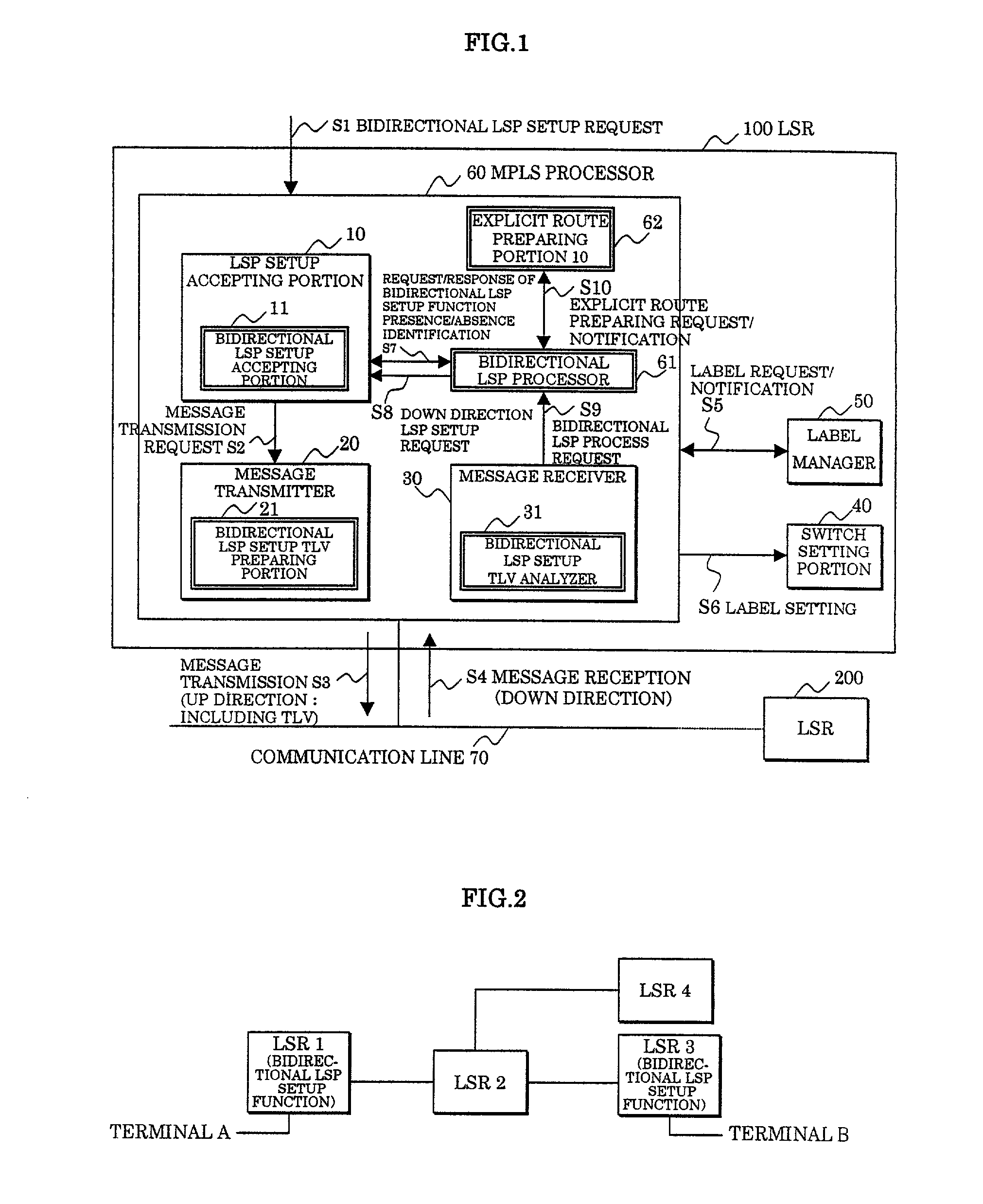
[0199] For example, the case where only the LSR1 has the bidirectional LSP setup function of the present invention in the network arrangement (2) shown in FIG. 12 is now assumed.

[0200] When receiving the up direction label request message from the LSR 1 in the same way as the embodiment (1), the LSR 3 transmits the label mapping message in the same way as the prior art process thereby establishing the up direction LSP.

[0201] However, since the LSR 3 is not provided with the bidirectional LSP setup function, the vendor-private TLV for setup acceptance as shown in FIG. 9 is not included in the label mapping message transmitted by the LSR 3, different from the case of the embodiment (1).

[0202] When receiving the label mapping message from the LSR 3, th...


PUM


Abstract

In a label switching router placed at one end of an LSP set by using CRLDP, a bidirectional LSP setup TLV preparing portion prepares a bidirectional LSP setup TLV included in a bidirectional setup label request message transmitted in an up direction to a label switching router placed at the other end of the LSP based on an external bidirectional LSP setup request accepted by a bidirectional LSP setup accepting portion, a bidirectional LSP setup TLV analyzer analyzes the bidirectional LSP setup TLV in the message when the message is received from the label switching router at the other end, a bidirectional LSP processor performs an LSP setup request in a down direction as opposed to the up direction based on the analyzed result by the bidirectional LSP setup TLV analyzer, and an explicit route preparing portion prepares an explicit route on which a router to be relayed in the down direction is prescribed, based on an explicit route preparing request from the bidirectional LSP processor and notifies the prepared route to the bidirectional LSP processor.

Description

[0001] 1. Field of the Invention[0002] The present invention relates to a Label Switching Router (hereinafter abbreviated as LSR), and in particular to a label switching router placed at an end of an LSP (Label Switched Path).[0003] 2. Description of the Related Art[0004] FIG. 28 shows a state in which a prior art router performs a packet transfer process by a software processing in the layer 3 by referring to a destination address. An IP packet P1 transmitted from an entrance router 1 reaches an exit router 3 through a middle router 2.[0005] On the other hand, FIG. 29 shows a packet transfer process by LSR's 1-3 which are routers used for MPLS (Multi Protocol Label Switching). The MPLS allocates 20 bits label to an IP communication traffic designated by an FEC (Forwarding Equivalence Class), thereby enabling switching by a hardware processing by a fixed length label (Shim header) in the layer 2.5. The MPLS is a technology for transferring a packet at a high speed.[0006] As shown in...

Claims


Application Information

Patent Timeline
IPC IPC(8): H04L45/50H04L47/80
CPCH04L45/50H04L45/00
Inventor ENOKI, TOHRUAOYAGI, YOSHIOOOHARA, YUJI
Owner FUJITSU LTD
Why Eureka
Try Eureka