Full cooling of main injectors in a two-headed combustion chamber

Inactive Publication Date: 2002-06-20
HISPANO SUIZA SA
View PDF4 Cites 15 Cited by
  • Summary
  • Abstract
  • Description
  • Claims
  • Application Information

AI Technical Summary

Benefits of technology

0006] The present invention seeks to provide a cooling circuit that makes it possible in main injectors to avoid such formation of coke at high temperature. An object of the invention is thus to provide complete protection for the fuel circuits of such injectors. Another object

Problems solved by technology

Unfortunately, while idling, and even more during stage burning, it is necessary to cool the main injectors, and most particularly to cool their ends that extend into the combustion chamber (often referred to as "tips") in order to avoid coking problems.
Nevertheless, those prior art systems suffer from the same major drawback, that

Method used


Image

  • Full cooling of main injectors in a two-headed combustion chamber
  • Full cooling of main injectors in a two-headed combustion chamber
  • Full cooling of main injectors in a two-headed combustion chamber

Examples


Embodiment Construction

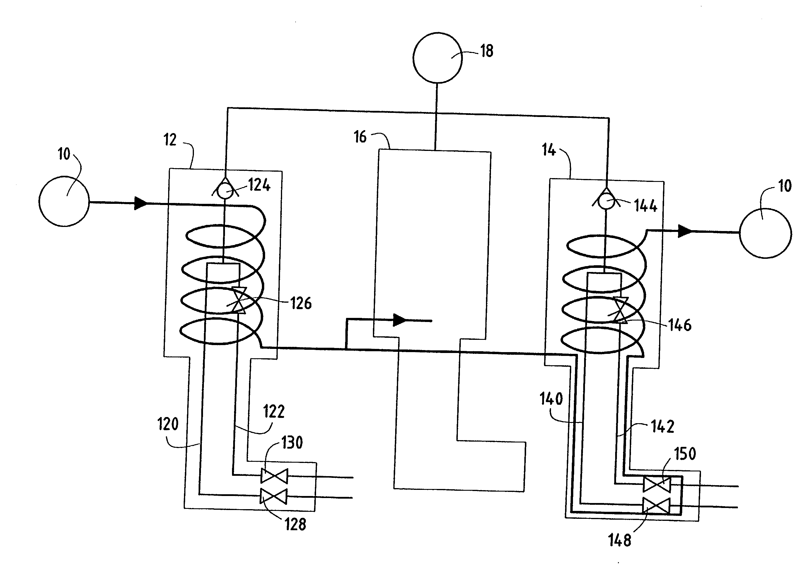
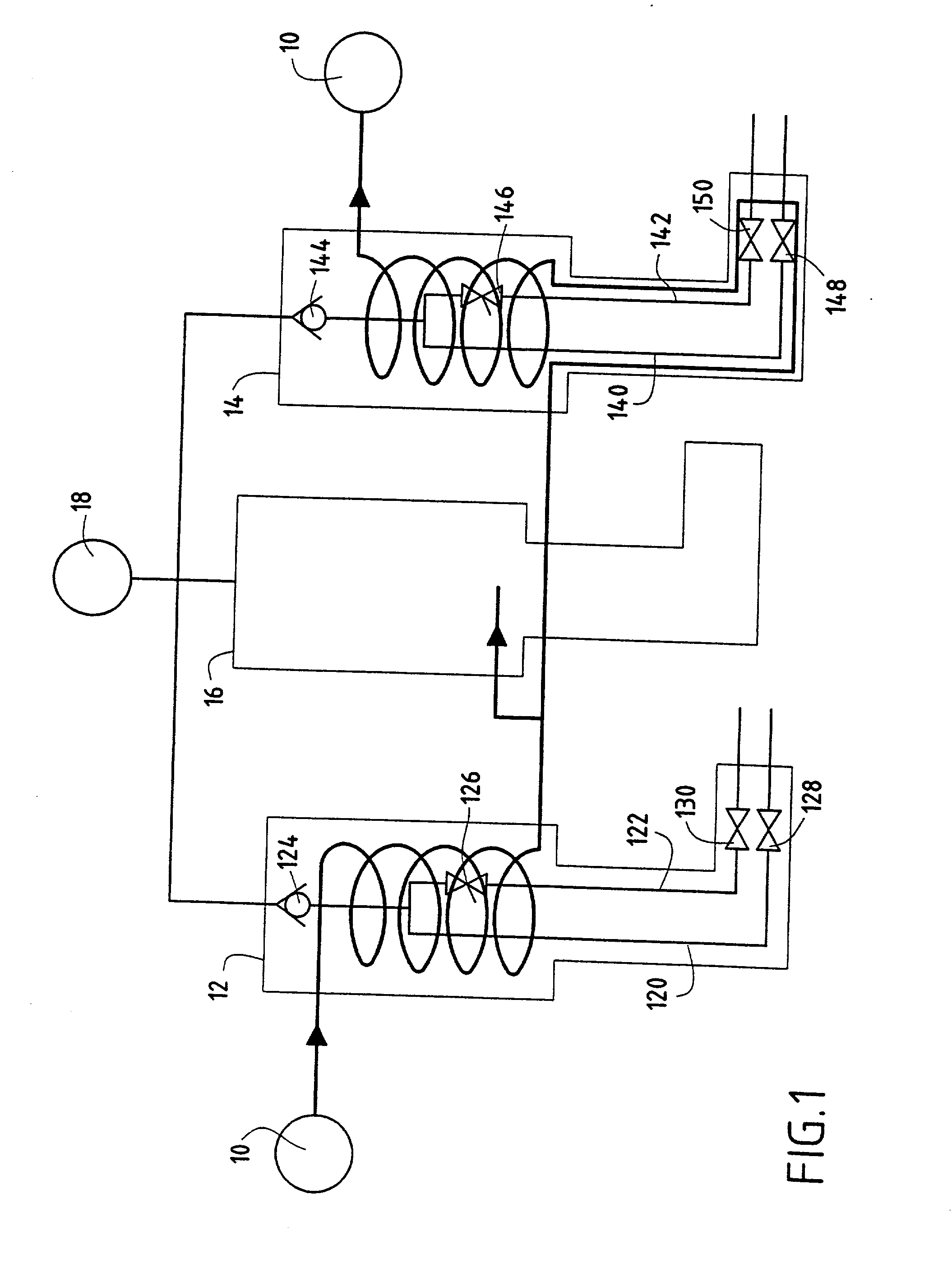
[0015] FIG. 1 is a schematic of the cooling circuit for fuel injectors in a two-headed annular combustion chamber of a turbomachine.

[0016] The cooling circuit is shown only for two injectors so as to make it easier to understand (such a combustion chamber can have as many as 16 pilot injectors and 32 main injectors, for example), and it is fed from a feed source 10 by an independent cooling fluid such as oil, water, fuel, or any other suitable fluid which passes successively through a "pilot" injector 12 for starting the turbomachine and enabling it to be idle (i.e. operate at low power), and is then fed in parallel to two "main" injectors 14, 16 (organized on the basis of one even rank and one odd rank), which injectors enable the machine to operate during cruising stages (and in particular at full power). The cooling fluid then returns to the feed source 10, thereby closing the cooling circuit (naturally and in conventional manner this circuit also includes a cooling fluid feed pu...


PUM


Abstract

An injector of a two-headed combustion chamber of a turbomachine has a first feed tube which is connected to an annular injection piece for discharging primary fuel into the combustion chamber. It also has a second feed tube surrounding the first feed tube and connected to a cylindrical endpiece for discharging secondary fuel into said combustion chamber. This endpiece has an annular channel of diameter that is greater than the diameter of the second feed tube and that extends over its entire length. A third tube is provided that surrounds the second tube and that is connected to a tubular separation element which is inserted in the annular channel of the cylindrical endpiece so as to form two annular spaces in which a cooling fluid can flow over 360° all the way to the end of the injector.

Description

[0001] The invention relates to the general field of fuel injectors in turbomachines, and more particularly it relates to cooling main injectors in a two-headed combustion chamber of such a turbomachine.PRIOR ART[0002] A turbojet or a turboprop (referred to below in the present description as a "turbomachine") having a twoheaded combustion chamber is started and kept idling using so-called "pilot" injectors only, while "main" injectors are additionally brought into use while cruising. Pilot injectors are fed with fuel on a permanent basis, whereas main injectors are fed only once the turbomachine is rotating at more than some minimum determined speed (generally lying in the range 10% to 30% of its nominal speed). Furthermore, during so-called "stage burning", only half of the main injectors are in operation, with the other half of the main injectors then being temporarily stopped.[0003] Unfortunately, while idling, and even more during stage burning, it is necessary to cool the main...

Claims


Application Information

Patent Timeline
IPC IPC(8): F23D11/36F23R3/28
CPCF23D11/36F23R3/283F23D2214/00
Inventor LAVIE, ALAINMARTELLI, STEPHANIEMICHAU, MARIONRODRIGUES, JOSETIEPEL, ALAIN
Owner HISPANO SUIZA SA
Why Eureka
Try Eureka