Heat-resistant assembly for protecting boiler tubes and method of assembling same

a technology for heating pipes and boiler tubes, which is applied in the direction of instruments, heat measurement, lighting and heating apparatus, etc., can solve the problems of block damage, block slipping, and block slipping,

Inactive Publication Date: 2002-06-20
MITSUBISHI HEAVY IND LTD
View PDF1 Cites 20 Cited by
  • Summary
  • Abstract
  • Description
  • Claims
  • Application Information

AI Technical Summary

Problems solved by technology

This results in both the bolt 23a and the nut 23b being exposed to combustion gases 50, which are likely to corrode them.
If this corrosion continues over time, heat resistant block 26 will be damaged, or it will separate from the tubes.
When this constraint or distortion occurs, the resulting thermal stress and that caused by the temperature differential between the interior and exterior of block 26 will damage the block.
This makes it difficult to securely fasten the block to the tubes, and the block has a tendency to become detached.
If this corrosion is allowed to continue, the block will be damaged or detached from the tubes.
If the angle of inclination of t...

Method used


Image

  • Heat-resistant assembly for protecting boiler tubes and method of assembling same
  • Heat-resistant assembly for protecting boiler tubes and method of assembling same
  • Heat-resistant assembly for protecting boiler tubes and method of assembling same

Examples


first embodiment

[0105] All other aspects of the configuration are identical to those of the first embodiment shown in FIGS. 1 and 2. Components which are the same in both embodiments have been given the same reference numerals.

[0106] FIGS. 5 through 8 show a third preferred embodiment of this invention.

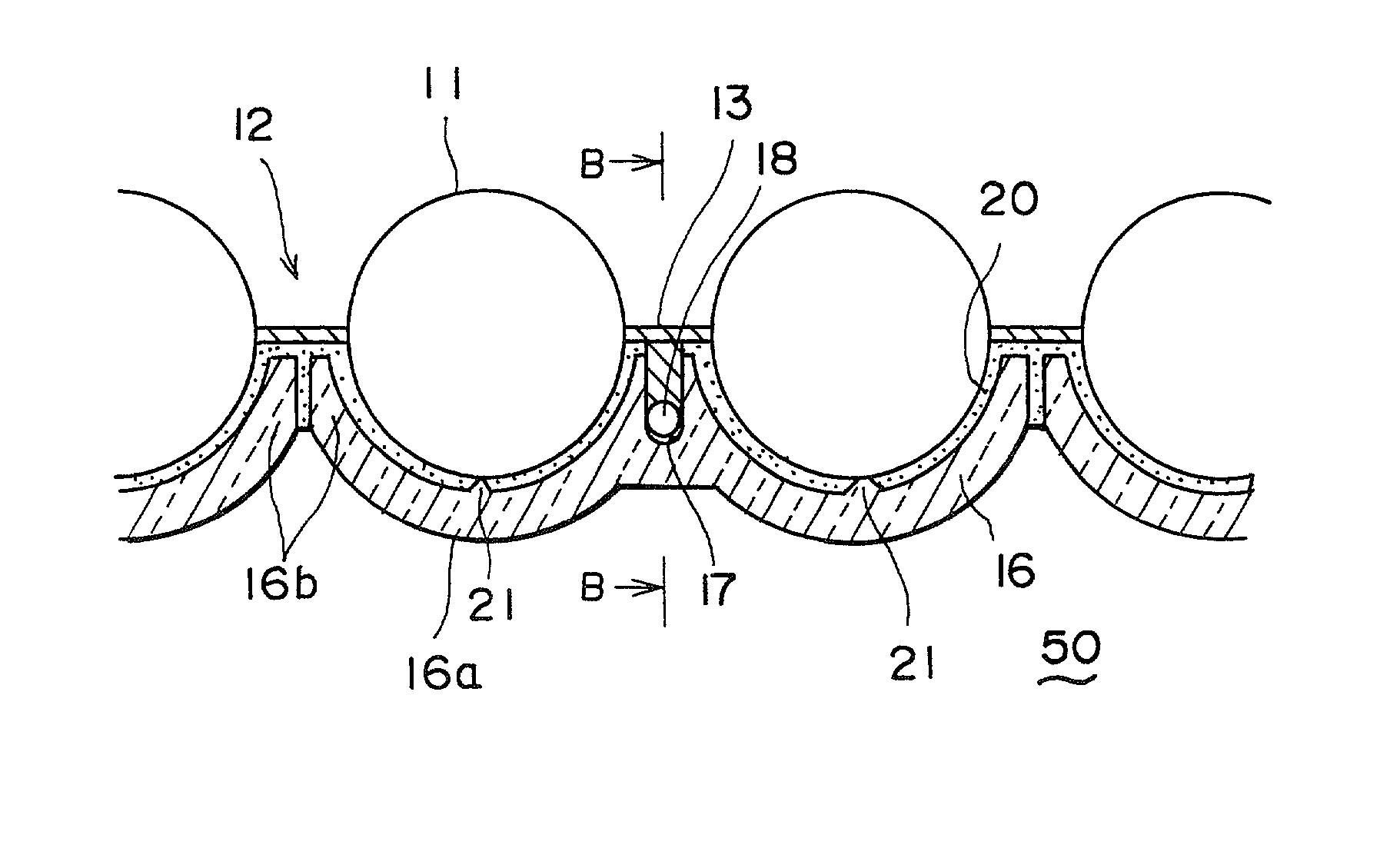
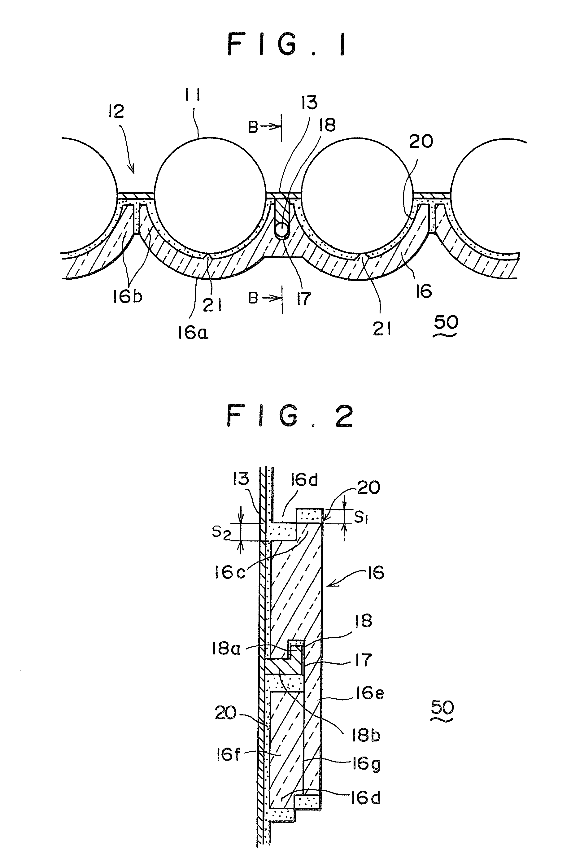
[0107] In these figures, 18 is an arm which projects from rib 13 on tube assembly 12. Just as in the first embodiment pictured in FIGS. 1 and 2, arm 18 consists of a projection 18b, which extends from the rib 13 at a right angle with respect to the surface of the rib, and a vertical portion 18a, which is bent upward at a 90.degree. angle from the projection 18b.

[0108] 17 is the indentation in heat-resistant block 16. Just as in the first embodiment discussed earlier, the arm 18 is shaped so that it can engage in this indentation.

[0109] In this embodiment, as can be seen in FIGS. 5 and 6, the space between mainly the vertical portion 18a of arm 18 and the surface of indentation 17 in heat-resistant bl...

third embodiment

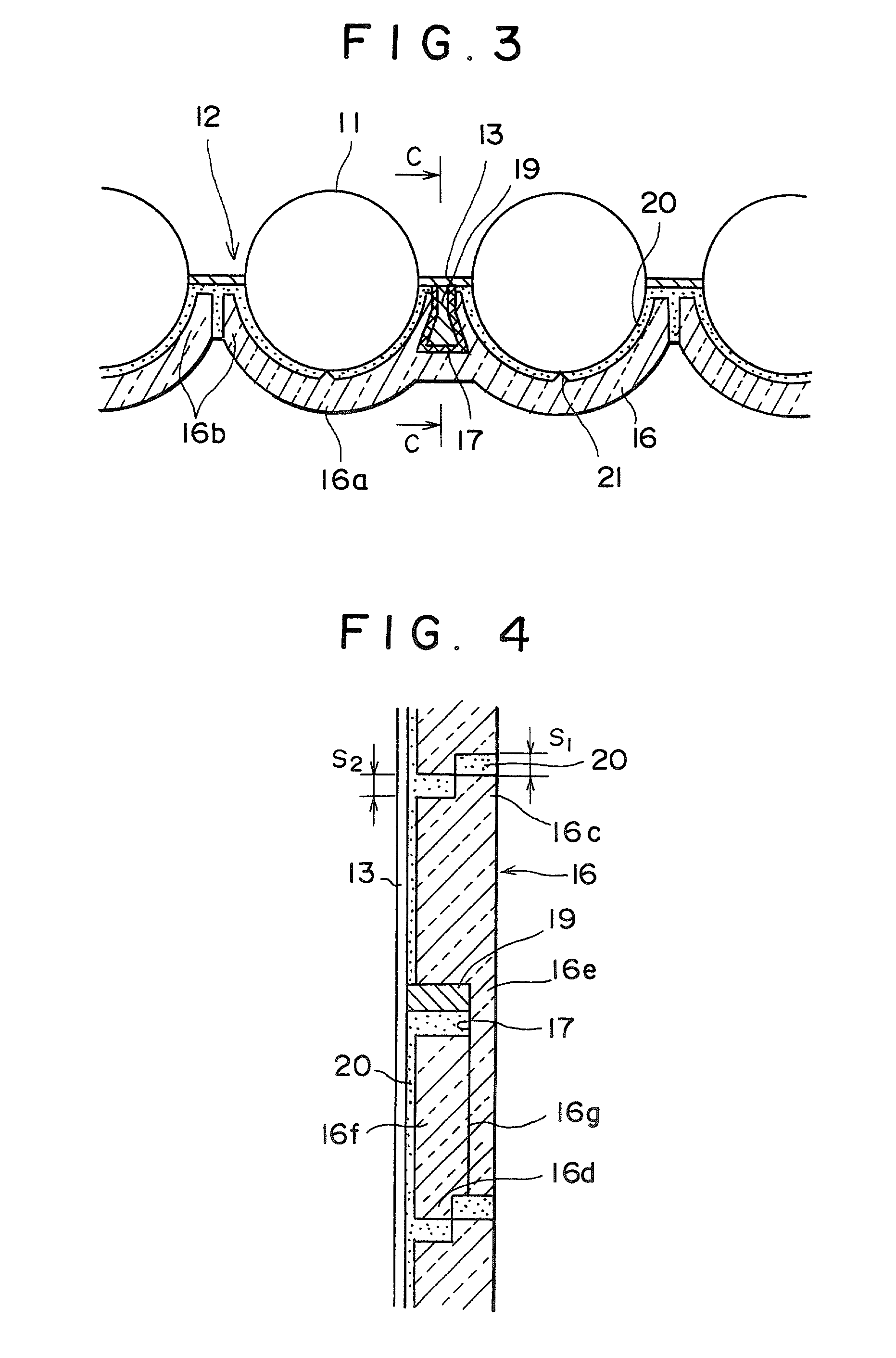
[0112] In this third embodiment, if the temperature of arm 18 of tube assembly 12 rises to 250.degree. C. during operation, the heat transmitted by arm 18 will cause the fusible substance 51 to melt, as is shown in FIGS. 7 and 8. This will create a gap 51a between the surface of arm 18 and the surface of indentation 17. As can be seen in the drawings, this gap 51a extends around the contour of arm 18.

[0113] The gap 51a provides a space to accommodate the thermal expansion of the heated arm 18. It absorbs the differential thermal expansion of the arm 18 and block 16, and it prevents damage to mortar 20 caused by this differential expansion in prior art designs.

[0114] All other aspects of the configuration are identical to those of the first embodiment shown in FIGS. 1 and 2. Identical components have been given the same reference numerals.

[0115] FIGS. 9 through 11 show a fourth preferred embodiment of this invention.

[0116] In these figures, 13 is the rib of tube assembly 12, and 18 i...


PUM

PropertyMeasurementUnit
Temperatureaaaaaaaaaa
Forceaaaaaaaaaa
Electrical resistanceaaaaaaaaaa

Abstract

This invention concerns a heat-resistant assembly having a heat-resistant block conformed to the contours of boiler tubes and the surface of their connecting rib. The heat-resistant assembly has an arm which protrudes from the surface of the rib toward the heat-resistant block and which has a catch on the end. The block has an indentation in which the catch on the arm engages. The block can be hung on or removed from the tube assembly by means of the arms and indentations. The heat-resistant assembly is further distinguished by the fact that a space is created between the end of the arm and the indentation of the block. A fusible substance, which will melt when the temperature of the arm exceeds a given value, is placed in the space. The heat-resistant assembly is further distinguished by the fact that an indentation is formed in the block in which a heat-resistant sleeve is adhered to engage the arm. This arrangement makes it possible to manufacture the heat-resistant block using press molding.

Description

[0001] This invention concerns a heat-resistant assembly for the water tubes of a heat-exchanger in a boiler to protect them from an atmosphere of super-heated gases, as well as a method of assembling this device.TECHNICAL BACKGROUND[0002] The water tubes which conduct heat in waste-heat boilers are protected from the heat conducted by the combustion gases and from their corrosive atmosphere by a heat-resistant block.[0003] FIGS. 19 through 21 show several examples of heat-resistant assemblies for the water tubes of a waste-heat boiler taken from the prior art.[0004] The design shown in FIG. 19 was proposed in Japanese Patent Publication (Kokai) 9-184602. In this drawing, 11 are boiler tubes and 13 are flat ribs to lend strength to tubes 11 by connecting them in either a horizontal or a vertical array.[0005] 26 are heat-resistant blocks of a ceramic material which are placed so as to protect the tubes 11 from combustion gases 50. The tubes 11 are protected from the heat of the combu...

Claims


Application Information

Patent Timeline
IPC IPC(8): F22B37/10F23M5/04F23M5/08
CPCF22B37/108F23M5/04F23M5/08Y10T29/4935Y10T29/49369Y10T29/49387Y10T29/49378F28F19/02F22B37/10
Inventor TERASHIMA, YASUHIRONAKAGAWA, YUJIINOUE, KEITAIKE, MINORU
Owner MITSUBISHI HEAVY IND LTD
Why Eureka
Try Eureka