Swivel wheel assembly with adjustable shock absorption

a technology of shock absorption and adjustable shock absorption, which is applied in the field of swivel wheel assembly, can solve the problem that the energy absorption cannot be custom-set based, and achieve the effect of quick assembly and disassembly

Inactive Publication Date: 2002-07-04
MARSHBURN BILL W
View PDF0 Cites 7 Cited by
  • Summary
  • Abstract
  • Description
  • Claims
  • Application Information

AI Technical Summary

Benefits of technology

0009] It is another object of the invention to provide swivel wheel which can be quickly assembled and disassembled.
0010] These and other objects of the present invention are achieved in the preferred embodiments disclosed below by providing a swivel wheel assembly. The wheel assembly includes a wheel axle. A vehicle wheel is rotatably mounted on the wheel axle. A shock-absorbing wheel fork is secured to opposite ends of the wheel axle. The wheel fork includes first and second elongated spaced-apart support arms located on opposite sides of the vehicle wheel. The support arms have respective distal and proximal ends. The distal ends define respective axle openings receiving the wheel axle. The proximal ends extend beyond a periphery of the vehic

Problems solved by technology

Because the spring compression is not adjustable, the resulting energy absorptio

Method used


Image

  • Swivel wheel assembly with adjustable shock absorption
  • Swivel wheel assembly with adjustable shock absorption
  • Swivel wheel assembly with adjustable shock absorption

Examples


Embodiment Construction

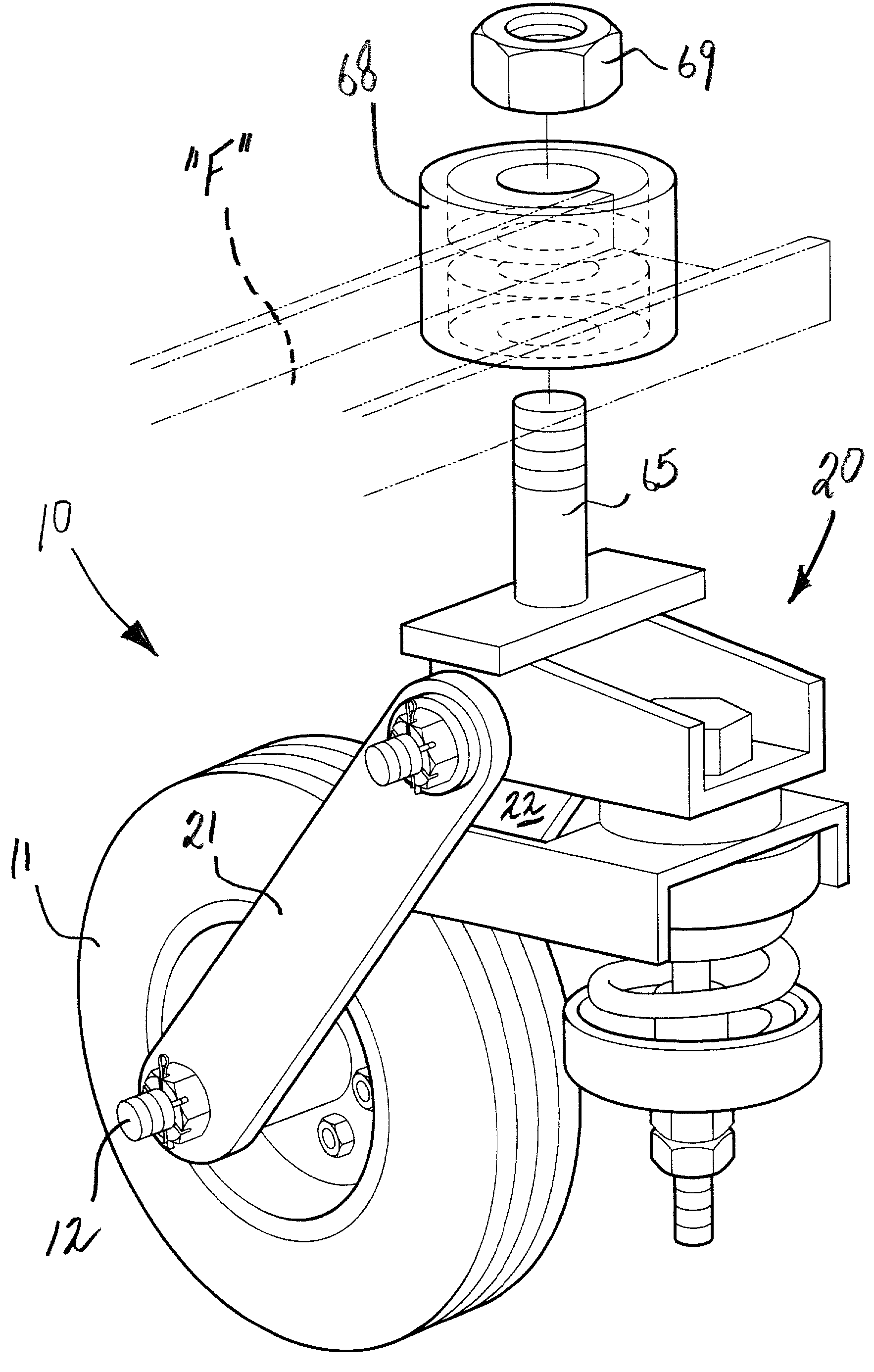
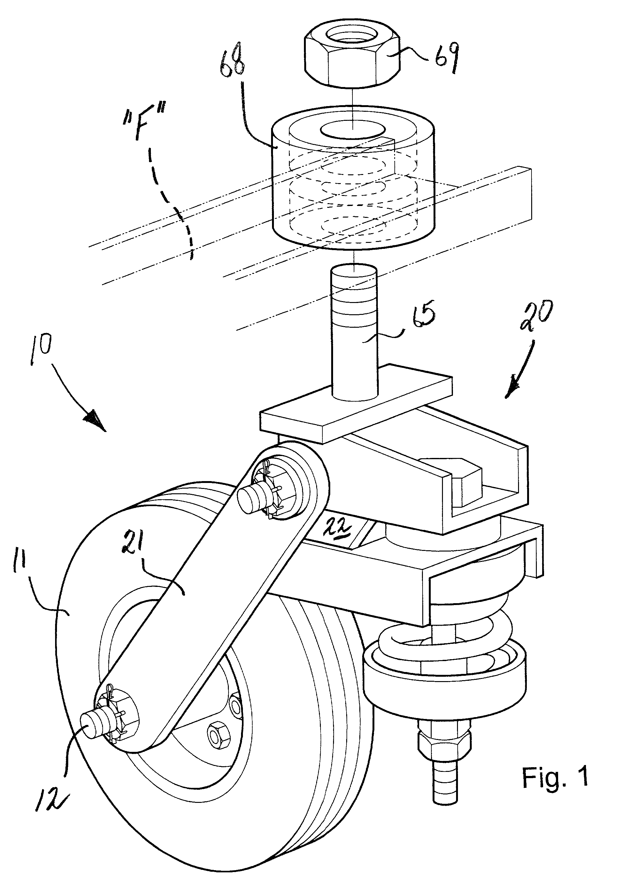
[0031] Referring now specifically to the drawings, a swivel wheel assembly according to the present invention is illustrated in FIG. 1, and shown generally at reference numeral 10. The wheel assembly 10 is especially applicable for use on utility vehicles, such as trailers, designed for being hauled. The trailer may be a three-wheeled vehicle with a single swivel wheel assembly 10 in the front and two conventional wheels in the rear, or a two-wheeled vehicle with two identical swivel wheel assemblies 10 on either side.

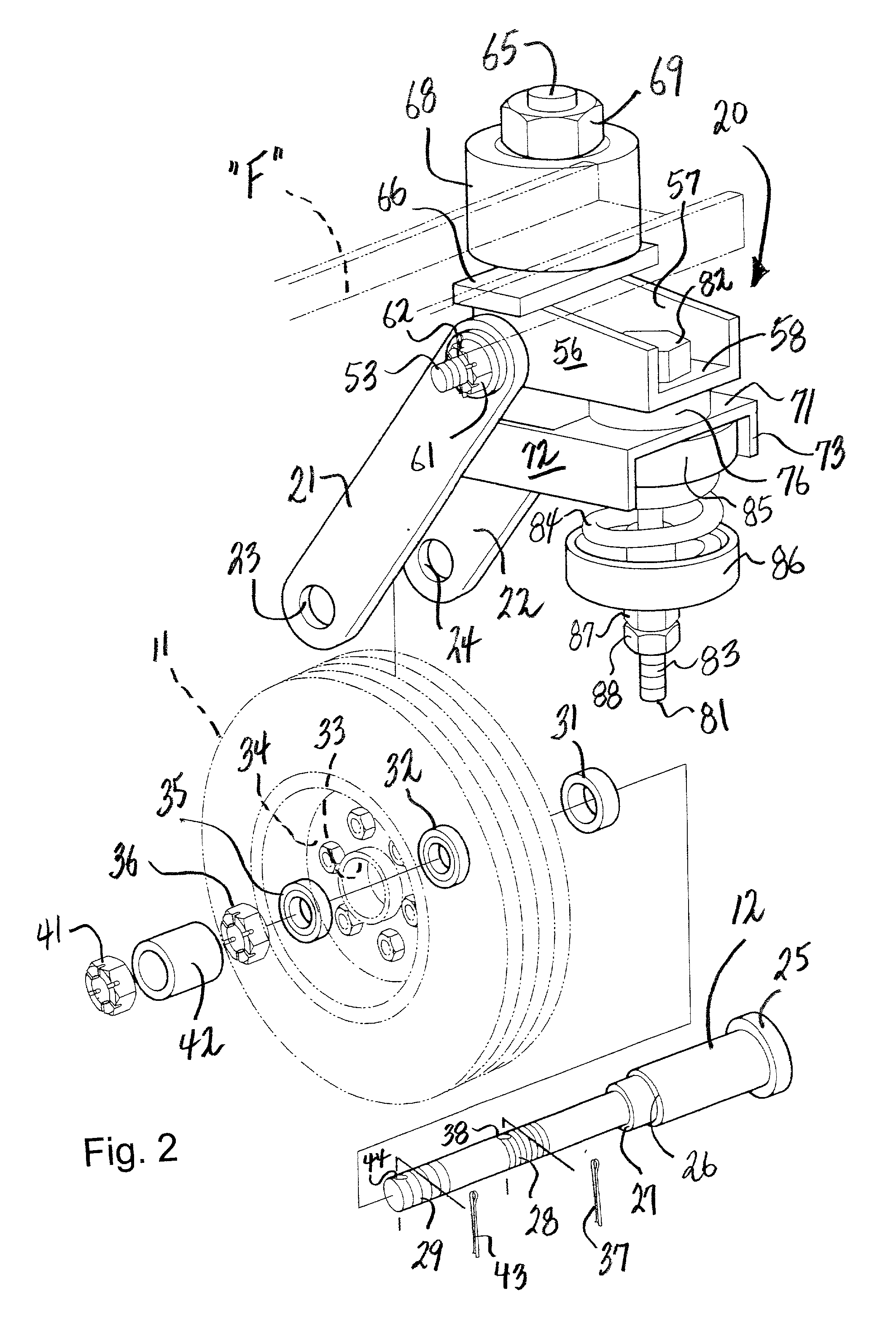
[0032] The swivel wheel assembly 10 includes a vehicle wheel 11 mounted for rotation on a wheel axle 12, and a shock-absorbing wheel fork 20 secured to the wheel axle 2 and an underframe "F" of the utility vehicle. As best shown in FIG. 2, the wheel fork 20 is constructed of first and second elongated, spaced-apart support arms 21 and 22 having respective distal and proximal ends. The distal ends define respective axle openings 23 and 24 which receive the wheel axle 12...


PUM


Abstract

A swivel wheel assembly includes a wheel axle, and a vehicle wheel rotatably mounted on the wheel axle. A shock-absorbing wheel fork is secured to opposite ends of the wheel axle. The wheel fork includes first and second elongated spaced-apart support arms located on opposite sides of the vehicle wheel. The support arms have respective distal and proximal ends. The distal ends define respective axle openings receiving the wheel axle. The proximal ends extend beyond a periphery of the vehicle wheel and define respective pin openings. A pivot pin extends through the pin openings formed with proximal ends of the first and second support arms. A base is carried by the pivot pin, and is adapted for pivoting movement about an axis defined by the pivot pin. A vertical swivel shaft is mounted on the base, and is adapted for connecting to an underframe of a vehicle to provide swivel movement of the vehicle wheel about an axis defined by the swivel shaft. An adjustable shock absorber is operatively connected to the base for dampening pivoting movement of the base relative to the vehicle wheel, thereby absorbing the energy of sudden shocks to the vehicle wheel during use.

Description

TECHNICAL FIELD AND BACKGROUND OF INVENTION[0001] This patent application claims priority to U.S. Provisional Patent Application Serial No. 60 / 259,455, filed on Jan. 3, 2001. This application relates to a swivel wheel assembly with adjustable shock absorption. The invention is especially applicable for use on utility vehicles, such as trailers, adapted for being hauled. The invention is easy to maneuver, and includes an adjustable shock absorber which allows custom stabilization of the vehicle for a smoother ride when towed. In a preferred embodiment, the utility vehicle has a conventional bumper pull and two identical laterally-spaced swivel wheel assemblies.[0002] Swivel wheel assemblies for utility vehicles are well known in the prior art. According to one such assembly described in U.S. Pat. No. 4,372,569, a vehicle wheel is rotatably mounted on a wheel axle beneath a shock absorber. A pair of wheel support arms are connected at one end to the wheel axis and at the opposite end ...

Claims


Application Information

Patent Timeline
IPC IPC(8): B60B33/04B60G3/00B60G7/00B60G11/16
CPCB60B33/045B60G3/00B60G7/001B60G11/16B60G2200/10B60G2200/445B60G2202/12B60G2204/124B60G2204/143B60G2204/148B60G2204/418B60G2204/43B60G2206/10B60G2300/37Y10T16/212
Inventor MARSHBURN, BILL W.
Owner MARSHBURN BILL W
Why Eureka
Try Eureka