Virtual computer system with dynamic resource reallocation
a virtual computer system and resource reallocation technology, applied in the field of virtual computer systems, can solve problems such as difficult to improve a response property of the system, the cpu time does not always represent the load condition of the computer system correctly, and the inability to automatically re-alloca
- Summary
- Abstract
- Description
- Claims
- Application Information
AI Technical Summary
Problems solved by technology
Method used
Image
Examples
embodiment 1
[0050] Embodiment 1
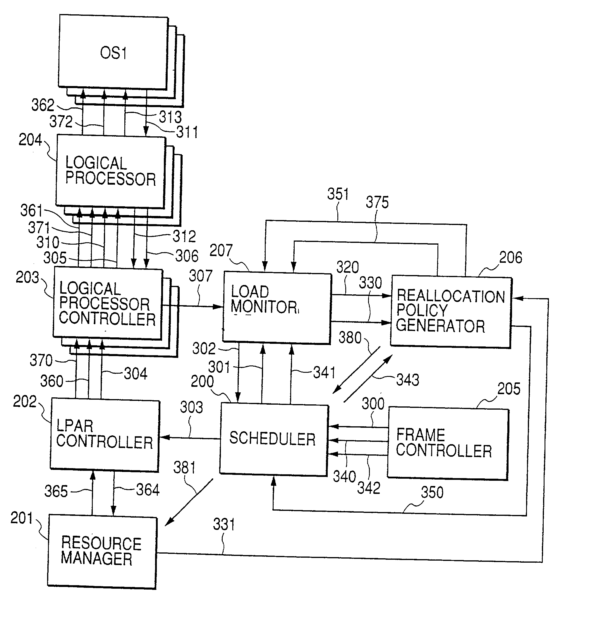
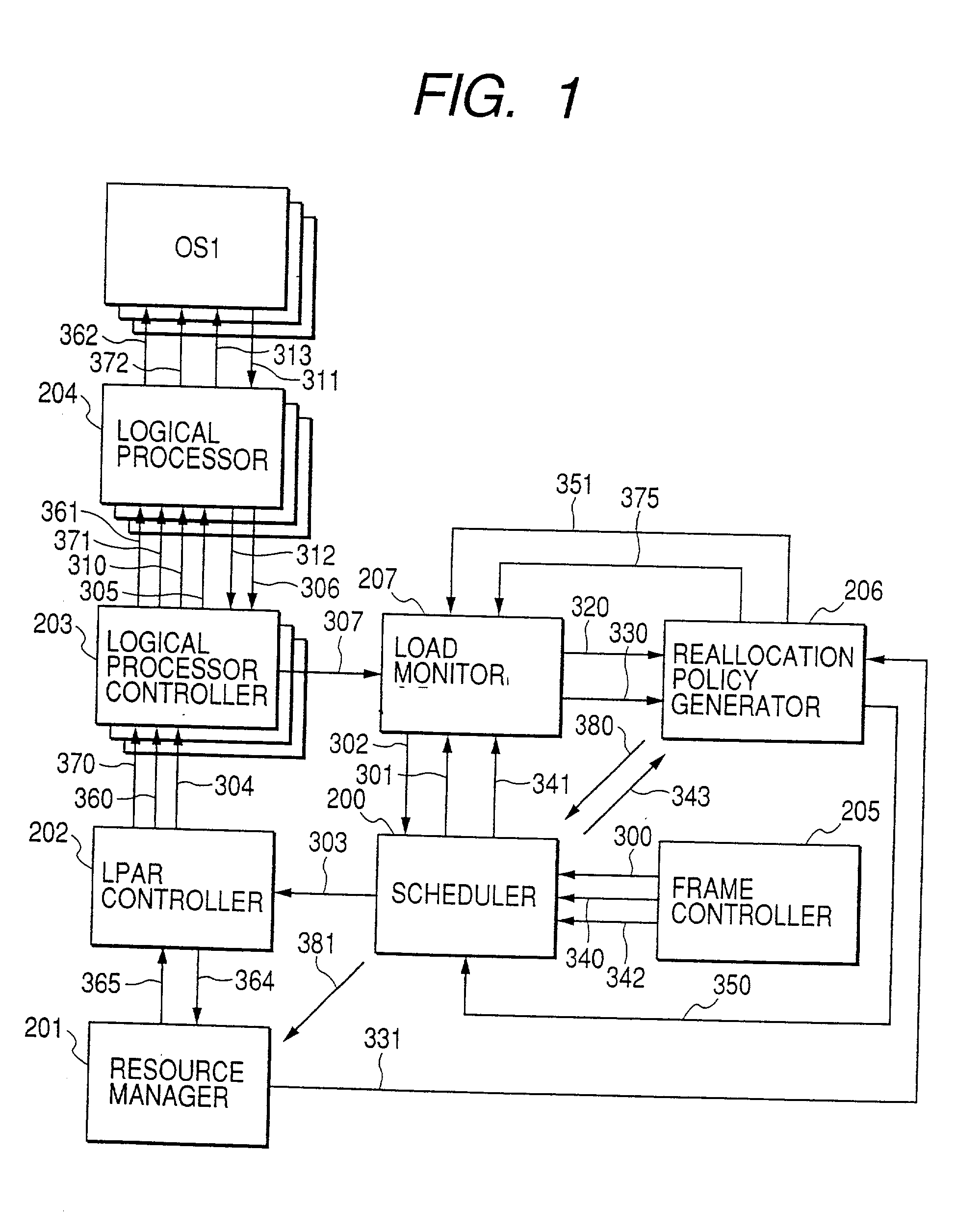
[0051] Hereinbelow, referring to FIG. 1, a process flow will be described, in which a load condition of LPAR measured by the OS on each LPAR is examined and dynamically reallocated. The term "load condition" as used herein means a length of queue for execution of process or a CPU occupation rate.
[0052] An operator of a virtual computer system sets, in a frame, a demand for examining a load condition of LPAR and time interval of the examination of the load. The frame controller 205 notifies the load monitor 207 of a monitoring demand and a monitoring interval of the LPAR load condition through the scheduler 200 (300, 301). Then, the load monitor 207 notifies the LPAR controller 2020 of a load condition examination demand (302, 303) through scheduler 200. The LPAR controller 202 examines a load condition of each logical processor 204 with respect to each logical processor controller 203 (305),and issues a demand (304) for transferring the examination results (306, 3...
embodiment 2
[0066] Embodiment 2
[0067] Hereinbelow, by using FIG. 17, process flow is described below, the process being from examination of a load condition of application operating on the LPAR to dynamic reallocation. The load condition of the application used herein is a response time of the application program process. For example, it means the response time of a transaction process such as retrieving a table from a data base so as to update contents of the table.
[0068] An operator of the virtual computer system requests to examine the load condition of the LPAR in a frame, and set a time interval to be examined. The frame controller 205 notifies the load monitor 207 of a monitoring demand and a monitoring interval about the LPAR load condition through the scheduler 200 (300, 301). Then, the load monitor 207 notifies the LPAR controller 202 of a load condition examination demand (302, 303) through the scheduler 200. The LPAR controller 202 examines a load condition of each logical processor ...
embodiment 3
[0081] Embodiment 3
[0082] The present embodiment is an example of a system, in which the reallocation policy generator 206 and the load monitor 207 are mounted to a program operating on a certain LPAR provided in the same virtual computer system according to Embodiment 2.
[0083] FIG. 19 shows a configuration of the present embodiment. A monitoring program 190 to be executed on LPAR5x issues reallocation demand of physical resources and monitoring of the load condition of LPAR50, . . . , LPAR5k.
[0084] The monitoring program 190 on the LPAR5x transfers the load condition examination demand to each LAPR50, . . . LPAR5k. At that time, as a communication method, the following is known as shown in Japanese Laid-Open Patent Publication No. 10-301795: a method for emulating the communication virtually by a hypervisor; a method using an IO channel; and a method using CPUs within LPARs whereas using channel to communicate with a computer outside the LPAR. In terms of a communication method bet...
PUM
 Abstract
Description
Claims
Application Information
 - R&D
- Intellectual Property
- Life Sciences
- Materials
- Tech Scout
- Unparalleled Data Quality
- Higher Quality Content
- 60% Fewer Hallucinations
Browse by: Latest US Patents, China's latest patents, Technical Efficacy Thesaurus, Application Domain, Technology Topic, Popular Technical Reports.
© 2025 PatSnap. All rights reserved.Legal|Privacy policy|Modern Slavery Act Transparency Statement|Sitemap|About US| Contact US: help@patsnap.com


