Pluggable transceiver module with extended release and removal lever

Inactive Publication Date: 2002-07-18
STRATOS INT
View PDF0 Cites 59 Cited by
  • Summary
  • Abstract
  • Description
  • Claims
  • Application Information

AI Technical Summary

Benefits of technology

0007] In view of the foregoing, it is an object of the present invention to provide

Problems solved by technology

The requirement of a tool for removing the transceiver module is not only inconvenient, but also prevents an operator from removing a transceiver m

Method used


Image

  • Pluggable transceiver module with extended release and removal lever
  • Pluggable transceiver module with extended release and removal lever
  • Pluggable transceiver module with extended release and removal lever

Examples


second embodiment

[0050] FIG. 4 illustrates the release lever 50. In the embodiment shown in FIG. 4, the sidable member 62 includes clips 70. The clips 70 and the slidable member 62 preferably are a single element formed out of thermal plastic. The clips 70 clasp onto the lever 38 during assembly of the release lever 50 onto the transceiver module 10. The clips 70 provide an alternative to gluing or heating the release lever 50 to the slidable member 62 during assembly. The clips 70 enable the release lever 50 to be mounted more quickly than bonding. Moreover, the release lever 50 can be easily removed by prying apart the clips 70; an option not available when using glue or heat bonding.

[0051] FIG. 5 illustrates the clips 70 shown in FIG. 4 from a different angle. FIG. 5 clearly shows the clips 70 clasp around the lever 38 in order to mount the release lever 50 to the transceiver module 10.

[0052] FIG. 6 illustrates the embodiment shown in FIGS. 4 and 5 wherein the release lever 50 is separated from t...

fourth embodiment

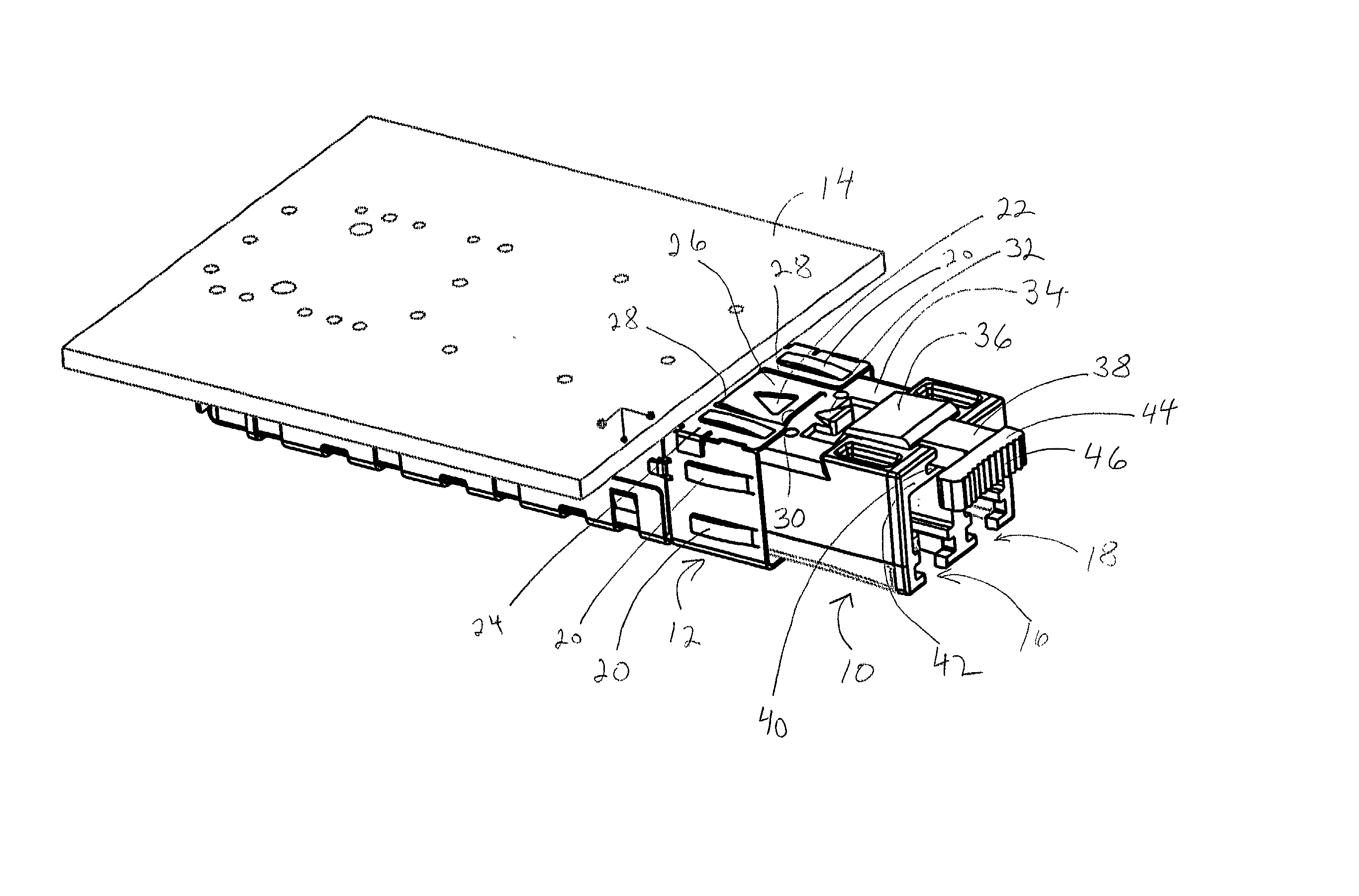
[0070] FIG. 21 shows a transceiver module 100 configured in accordance with the present invention. A housing 101 includes a top 102, sides 104, and bottom 106. An input 108 and output 110 are shown at the front 112 of the housing 101. A release and removal lever 114 is shown extending out of a slot 116 in the front 112 of the housing 101.

[0071] In accordance with the present invention, the release and removal lever 114 includes a recess 120 at the end of the release and removal lever 114. A person can insert his or her fingernail into the recess 120 so as to provide a secure grip on the transceiver module 100 and remove the transceiver module 100. After an operator presses on the release and removal lever 114 in order to release the transceiver module 100 from a socket or receptacle, then the operator can remove the transceiver module 100 by inserting their fingernail into the recess 120 and pulling the transceiver module from the socket.

[0072] FIG. 22 shows the release and removal ...


PUM


Abstract

A pluggable transceiver module having a housing with a first side and a face perpendicular to the first side, and a tab extending above the surface of the first side sized to mate with a slot in a receptacle for the housing, a wedge slidably mounted on the first side proximate the tab, and a lever attached to the wedge extending beyond the face of the housing, wherein pressing the lever causes the wedge to slide between the tab and the slot on the receptacle and remove the tab from within the slot, thereby releasing the transceiver module from the receptacle, and the lever further including a recess enabling a person to at least partially insert a fingernail to easily grip and remove the pluggable transceiver module from the receptacle.

Description

CONTINUATION-IN-PART APPLICATION[0001] This application is a continuation-in-part (CIP) application of U.S. patent application having Ser. No. 09 / 727,943, filed on Nov. 30, 2000, and titled "Transceiver Module with Extended Release Lever."[0002] The present invention relates generally to transceiver modules, and more particularly, to a pluggable transceiver module having an extended release and removal lever.[0003] Optoelectronic transceivers are utilized to interconnect circuit cards of communication links and other electronic modules or assemblies. Various international and industry standards define the type of connectors used to interface computers to external communication devices such as modems, network interfaces, and other transceivers. A well-known type of transceiver module developed by an industry consortium and known as a Gigabit Interface Converter (GBIC) provides an interface between a computer and an Ethernet, Fibre Channel, or other data communication environment. U.S...

Claims


Application Information

Patent Timeline
IPC IPC(8): G02B6/38G02B6/42
CPCG02B6/389G02B6/3897G02B6/4201G02B6/4246G02B6/4261G02B6/428
Inventor MEDINA, RAUL
Owner STRATOS INT
Why Eureka
Try Eureka