
Method for manufacturing electrode plate group for prismatic battery

a technology of prismatic batteries and electrode plates, which is applied in the direction of cell components, sustainable manufacturing/processing, and flat cell grouping. it is difficult to avoid the variation in the distribution of active materials between different positions on the large plate, and achieves the imbalance of capacity between the positive and negative electrodes

Inactive Publication Date: 2002-08-08
PANASONIC CORP +1
View PDF2 Cites 0 Cited by
  • Summary
  • Abstract
  • Description
  • Claims
  • Application Information

AI Technical Summary

Benefits of technology

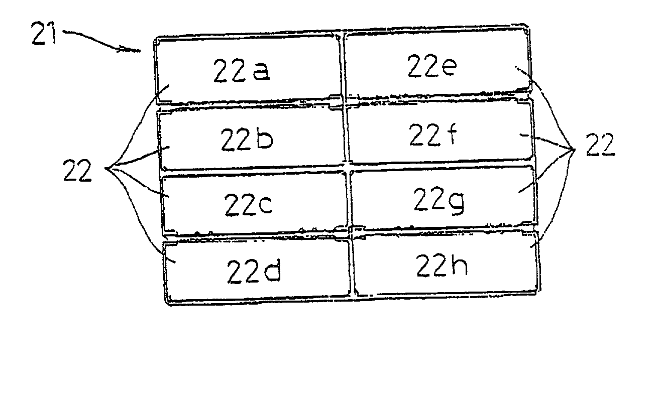
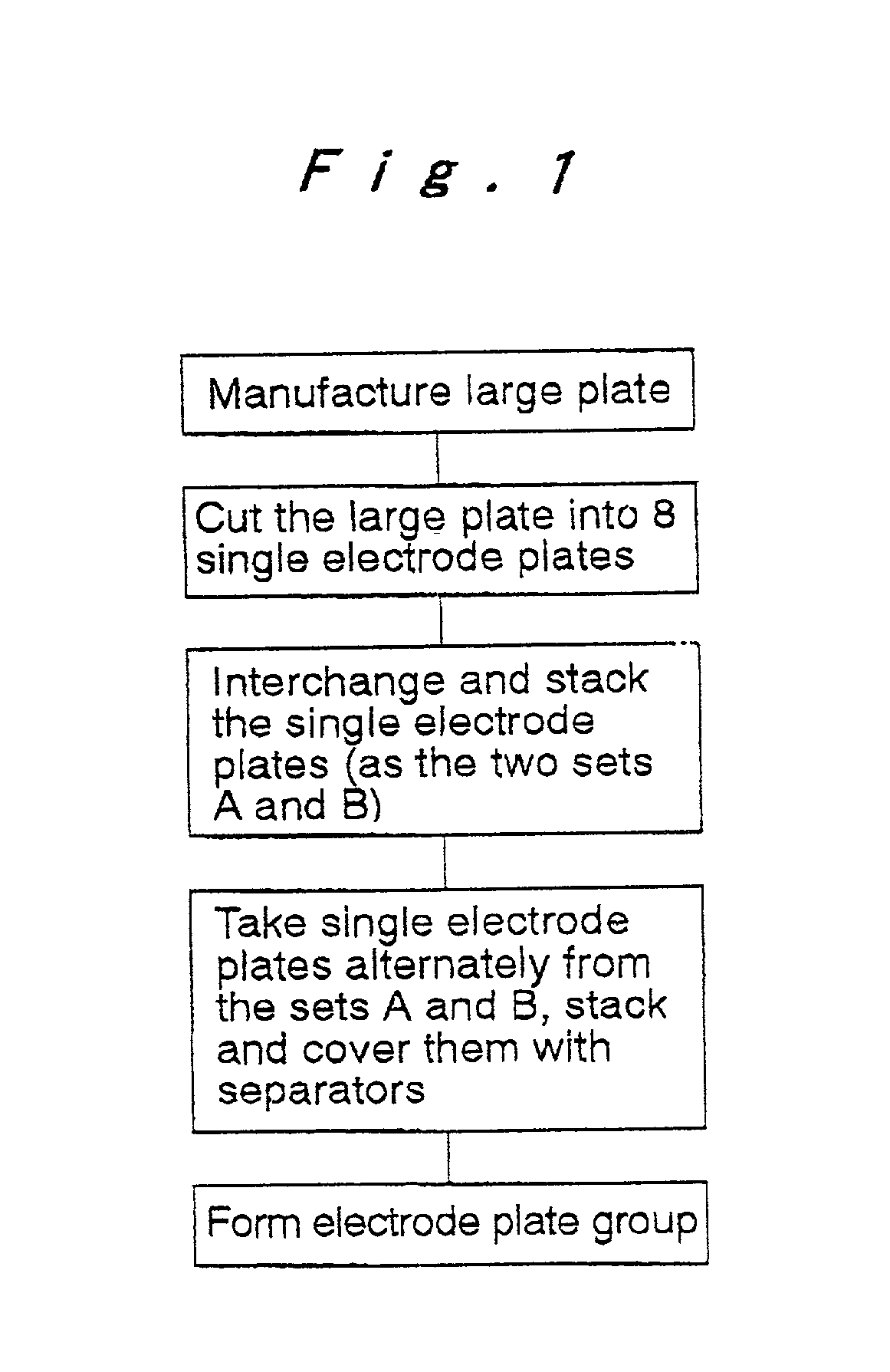
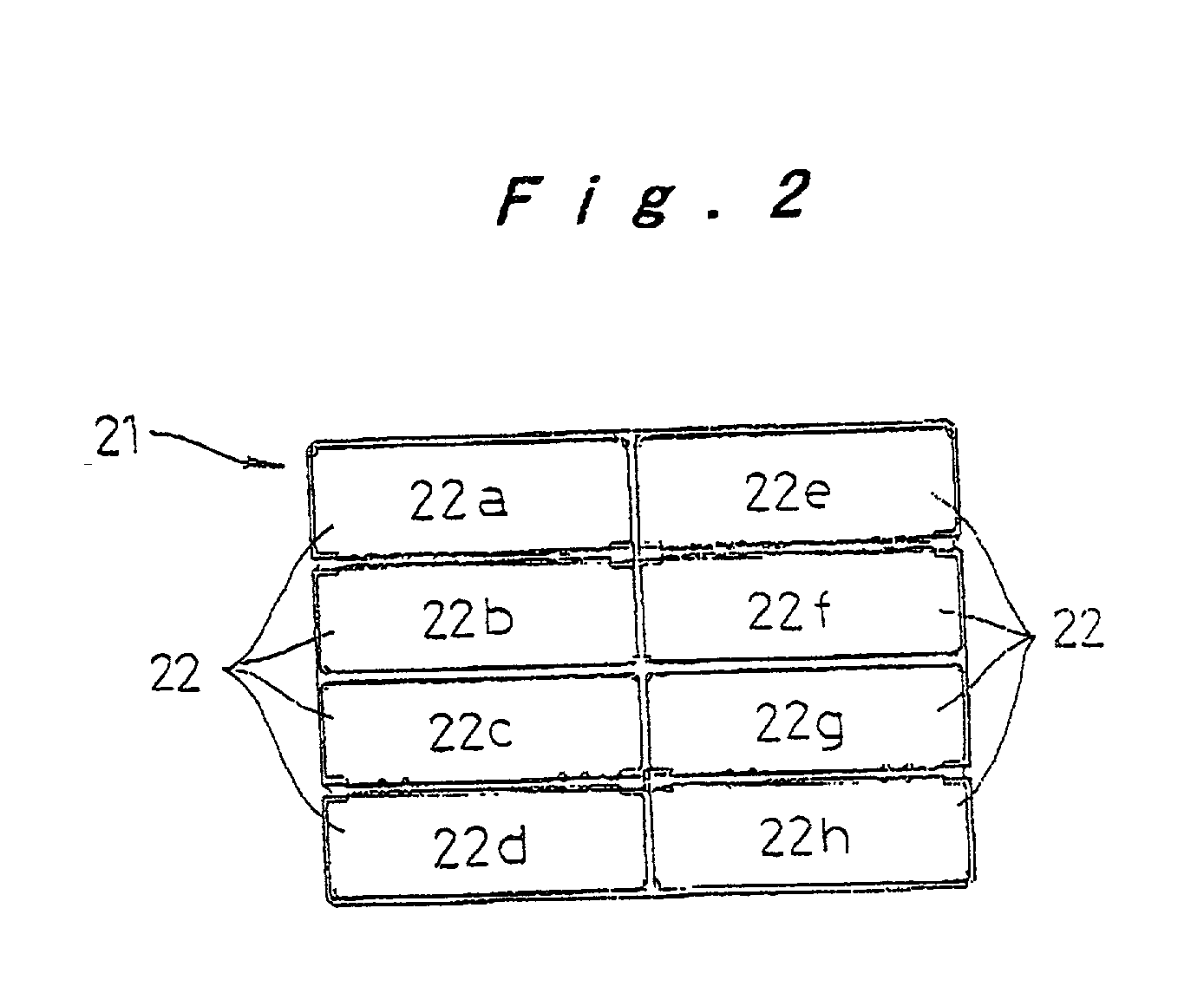
[0013] A method for manufacturing an electrode plate group for a prismatic battery according to the invention includes the steps of manufacturing a large plate from which a plurality of single electrode plates that form the electrode plate group are cut, cutting a plurality of single electrode plates from the large plate, stacking the single electrode plates by grouping together single electrode plates from different positions on the large plates, and forming the electrode plate group by successively taking single electrode plates from the stacked single electrode plates and alternately stacking the taken single electrode plates with single electrode plates of the opposite polarity. When stacking the single electrode plates cut from the large plates, single electrode plates from different positions on the large plates are grouped together, so that there is no variation in weight between the sets of stacked single electrode plates. Single electrode plates are successively taken from the stacks and used to form an electrode plate group, the weight of which is therefore within a predetermined range. In addition, by merely having single electrode plates from different positions on the large plates grouped together during stacking, high-output, long-life prismatic batteries are manufactured without requiring a weight sorting device or the like and without increases in equipment costs or decreases in productivity.
[0014] An operation, which (i) divides the single electrode plates cut from the large plate into a plurality of different kinds of sets that are each composed of a plurality of single electrode plates and (ii) interchanges the positions of the single electrode plates composing a set by rotating the single electrode plates about a central point, may be performed with a combination of sets that are rotated and an order in which the sets are rotated being successively changed for each large plate so as to interchange the positions of the single electrode plates. A simple, low-cost construction can be used to support and rotate a set of single electrode plates so that single electrode plates from different positions on the large plates are stacked together.

Problems solved by technology

If such electrode plates were to be manufactured individually, this would result in extremely poor productivity.
When single electrode plates are manufactured from a large plate, however, it is extremely difficult to avoid variations in the distribution of active materials between different positions on the large plate.
As one example, when an electrode plate group is formed by stacking the heaviest positive electrode plates, the lightest negative electrode plates and separators, there will be a marked imbalance in capacity between the positive and negative electrodes.
This leads to poor absorption of gas during charging, resulting in a rise in internal pressure and a risk of the battery leaking.
Alternatively, this may lead to the safety vent opening frequently, resulting in a reduction in the cycle life of the battery due to a decrease in the amount of electrolyte, etc.
Accordingly, this method has a drawback of increased equipment costs.
This increases equipment costs and there is the further problem of the time required to measure the capacities of batteries, which lowers productivity.

Method used


Image

  • Method for manufacturing electrode plate group for prismatic battery
  • Method for manufacturing electrode plate group for prismatic battery
  • Method for manufacturing electrode plate group for prismatic battery

Examples


example 2 example

Art Sorting by No No No Yes weight? Interchanging Yes Yes No No of plates? Alternate Set Yes No No No A and Set B? Variation in .+-.2.1% .+-.3.5% .+-.7.0% .+-.2.0% capacity

[0038] A variation in capacity of .+-.7.0% was observed for the comparative example where the electrode plate groups are formed without interchanging the single electrode plates. For Example 1, however, the variation in capacity was kept to just .+-.2.1%, so that variations in capacity are suppressed to a similar extent as the related art with high productivity and at low cost. Note that there is slightly more variation in Example 2 where the single electrode plates are not alternated between the sets A and B.

[0039] It should be noted that while the above embodiment is described using an example where the arrangement positions of the single electrode plates are interchanged by successively repeating operations with four patterns that are combinations of a first operation where a set composed of all the single elec...


PUM

PropertyMeasurementUnit
polarityaaaaaaaaaa
weightaaaaaaaaaa
weightsaaaaaaaaaa

Abstract

A method for manufacturing an electrode plate group for a prismatic battery includes the steps of manufacturing a large plate from which a plurality of single electrode plates that form the electrode plate group are cut, cutting a plurality of single electrode plates from the large plate, stacking the single electrode plates by grouping together single electrode plates from different positions on the large plates, and forming the electrode plate group by successively taking single electrode plates from the stacked single electrode plates and alternately stacking the taken single electrode plates with single electrode plates of the opposite polarity.

Description

[0001] The present disclosure relates to subject matter contained in priority Japanese Patent Application No. 2000-378716, filed on Dec. 13, 2000, the contents of which is herein expressly incorporated by reference in its entirety.[0002] 1. Field of the Invention[0003] The present invention relates to a method for manufacturing an electrode plate group for a prismatic battery, and more particularly to a method for manufacturing an electrode plate group having little variation in weight at low cost and with high productivity.[0004] 2. Description of Related Art[0005] In a prismatic battery, an electrode plate group is formed by stacking rectangular-shaped positive electrode plates and negative electrode plates with separators interposed therebetween. This electrode plate group is accommodated in a prismatic battery case along with an electrolyte, and an opening at the top of the battery case is closed by a lid having a safety vent.[0006] Electrode plates such as positive electrode pl...

Claims


Application Information

Patent Timeline
Patent Type & Authority Applications(United States)
IPC IPC(8): H01M10/04H01M2/02H01M4/04H01M4/26H01M4/82H01M6/00H01M6/46H01M10/28
CPCH01M2/0217H01M4/0402H01M4/26H01M10/28Y02E60/124Y10T29/49112Y10T29/49108H01M50/103Y02E60/10Y02P70/50
Inventor MATSUMURA, JUNSUZUKI, KOHEI
Owner PANASONIC CORP
Learn More