Liquid container, elastic member for liquid container, and recording apparatus

a technology for liquid containers and elastic parts, which is applied in the direction of printing, etc., can solve the problems of contaminating the main assembly of the recording apparatus, the area around, and the drip of ink from the ink delivery hole 131, and the leakage of liquid not easy to occur through

Inactive Publication Date: 2002-09-05
CANON KK
View PDF0 Cites 23 Cited by
  • Summary
  • Abstract
  • Description
  • Claims
  • Application Information

AI Technical Summary

Problems solved by technology

Therefore, there is a possibility that ink will drip from the ink delivery hole 131 and contaminate the recording apparatus main assembly, and the area around the liquid container.
Therefore, even if the cylindrical member is removed after long term continuous penetration of the cylindrical member in the elastic member, the leakage of the liquid does not easily occur through the connection opening.

Method used


Image

  • Liquid container, elastic member for liquid container, and recording apparatus
  • Liquid container, elastic member for liquid container, and recording apparatus
  • Liquid container, elastic member for liquid container, and recording apparatus

Examples


first embodiment

[0103] The first object of the present invention is to provide a liquid container, which can be mounted into, or dismounted from, the main assembly of an ink jet recording apparatus, without leaking the liquid therein, even after it is left alone for a long period of time, or it is left alone, with a cylindrical needle penetrating it, for a long period of time. The concrete examples of such a liquid container is disclosed in the description of the present invention.

[0104] The second object of the present invention is to pr2vent the phenomenon that as a cylindrical needle is pushed through the sealing member of a liquid container, the elastic member is deformed in such a manner that the portion of the elastic member around the needle, on the needle entry side of the sealing member, is pulled into the elastic member, whereas the portion of the elastic member around the needle, on the side opposite to the needle entry side, conically peels away from the needle, and thereby, to provide ...

embodiment 1

[0122] (Embodiment 1)

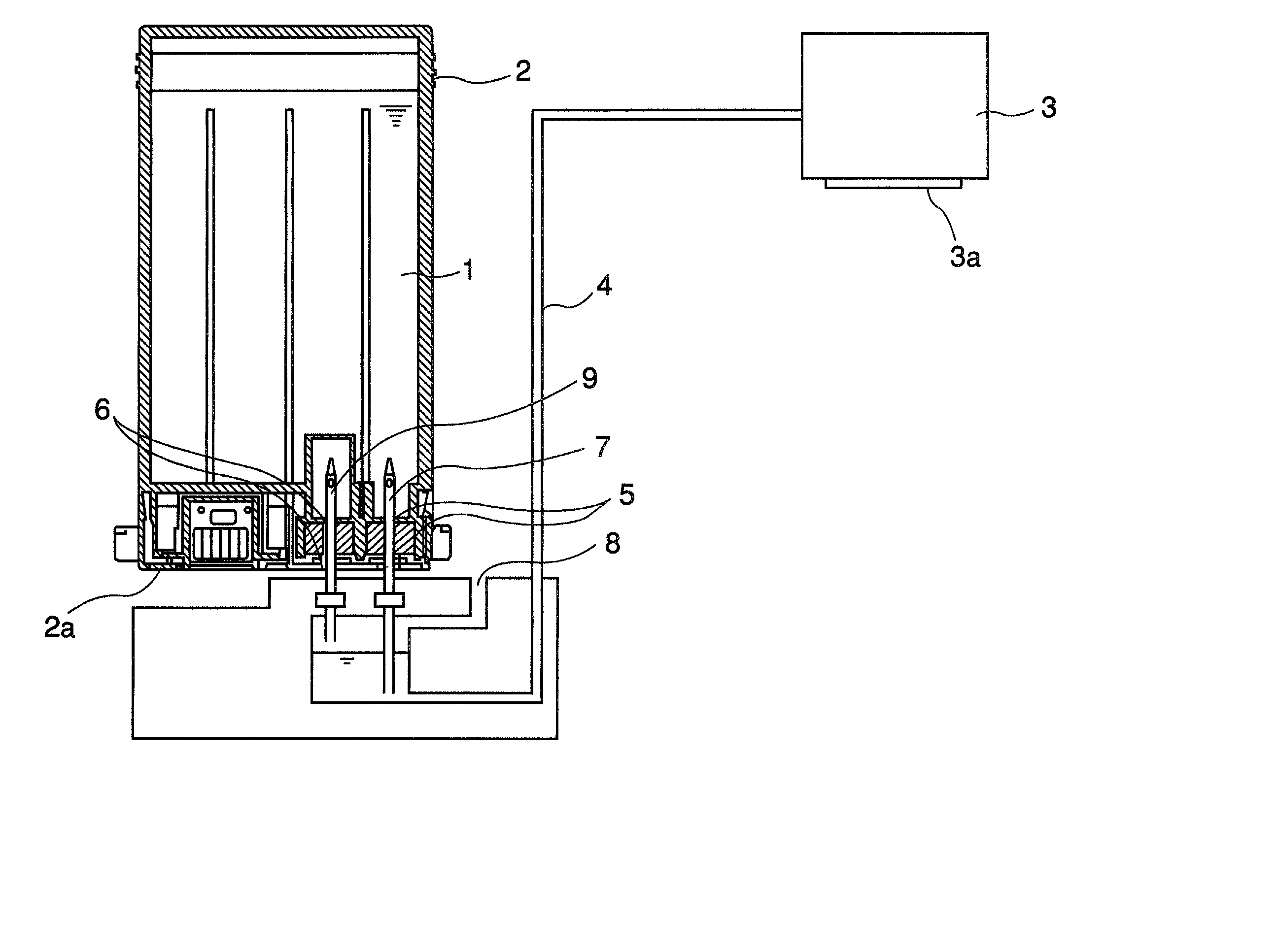
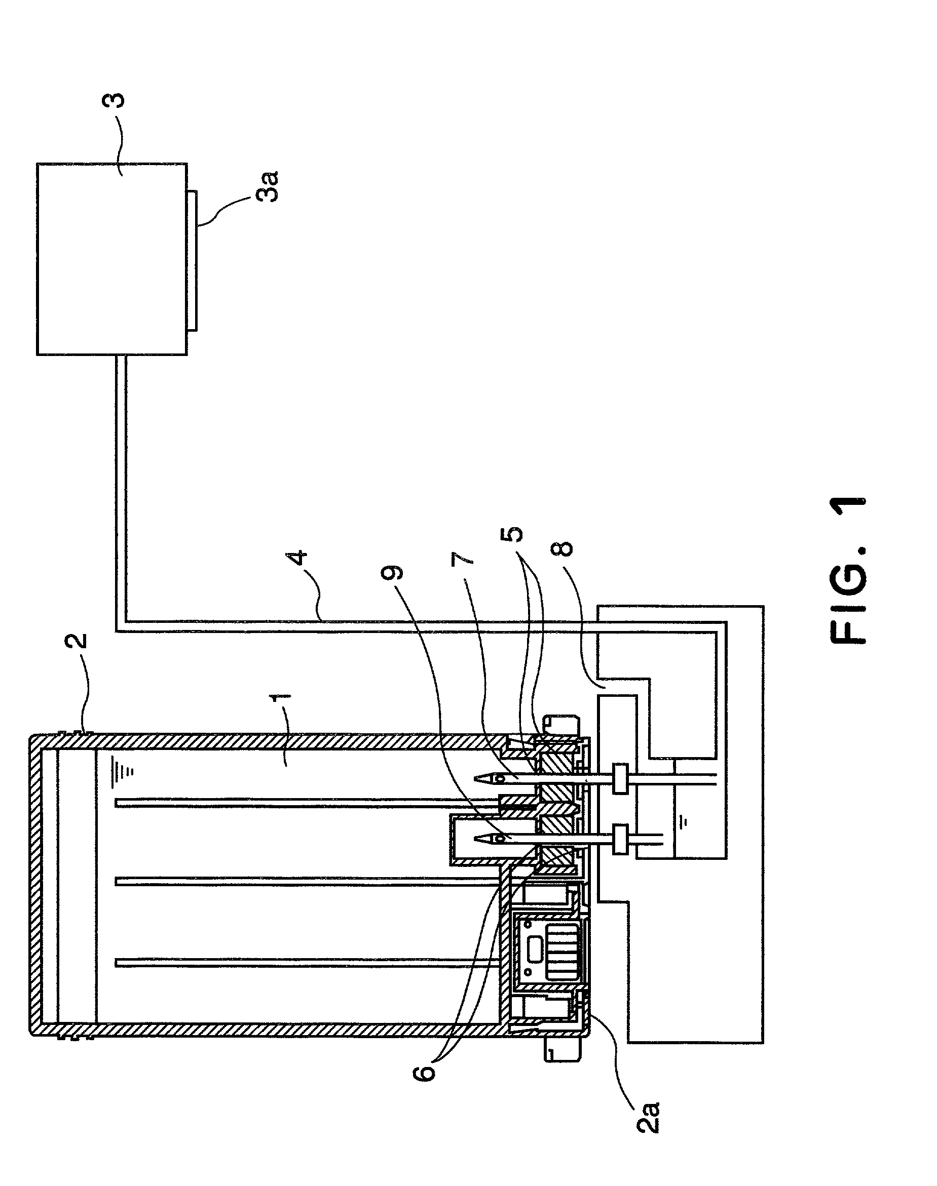
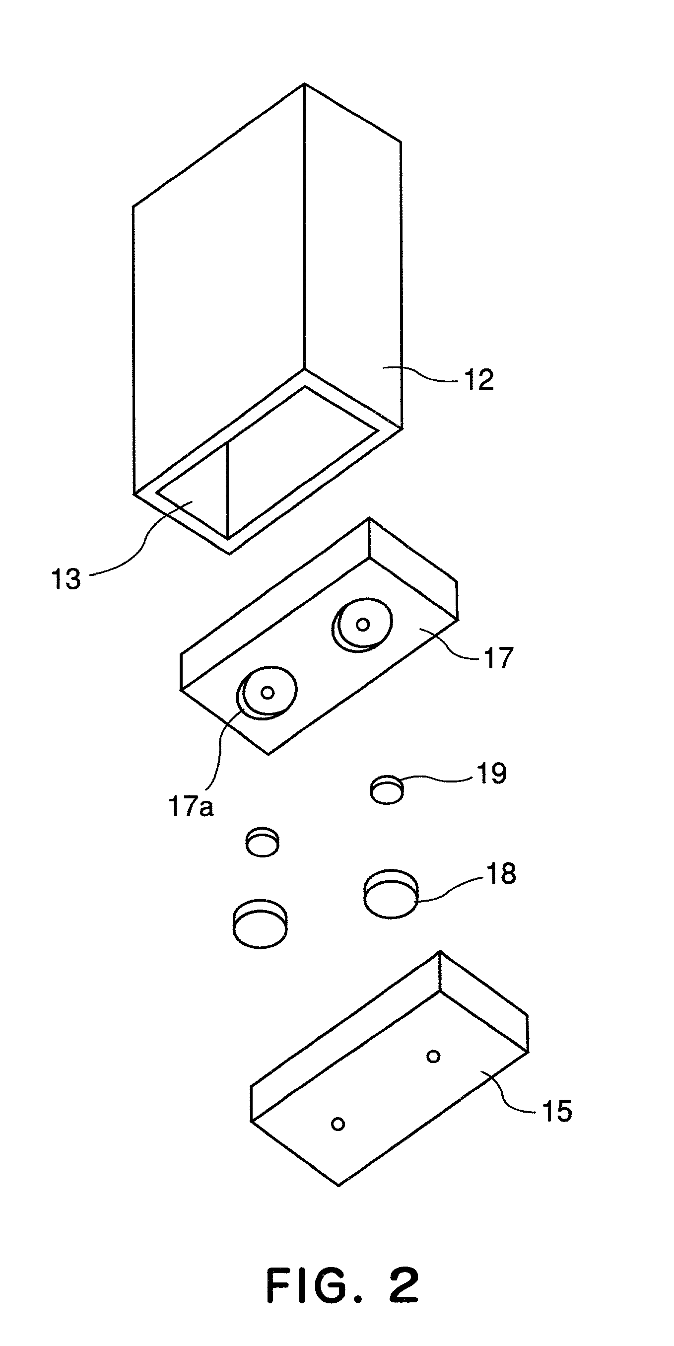
[0123] Next, referring to FIGS. 2-9, the first embodiment of the present invention will be described.

[0124] In this embodiment, the compressed elastic member 18 is used as an elastic member which is subjected to compressive force as it is placed into the liquid container 2. In comparison, the uncompressed elastic member 19 is not subjected to compressive force as it is placed into the liquid container 2. It is subjected to compressive force for the first time as the connective needles (cylindrical members) are inserted.

[0125] In the following descriptions of the embodiments of the present invention, "uncompressed state" means such a state of the elastic member that the compression pressure generated in the elastic member by the external force is not present in the elastic member.

[0126] FIG. 4 is an external view of the compressed elastic member 18 shown in FIG. 2: FIG. 4(a) is a perspective external view; FIG. 4(b) is a plan view; and FIG. 4(c) is a side view. F...

embodiment 2

[0149] (Embodiment 2)

[0150] Next, referring to FIGS. 11-17, the second embodiment of the present invention will be described. The structural components in this embodiment, which are identical to those shown in FIGS. 1-3, are given the same referential codes as those given to the corresponding structural components in FIGS. 1-3, so that a part of the description of the first embodiment can be used as the description of some of the structural components in this embodiment.

[0151] FIG. 11 is a schematic drawing for describing the configuration of the elastic member placed in the recess of the elastic member holding member 17 of the liquid container: FIG. 11(a) is an external perspective view of the elastic member; FIG. 11(b), a plan view of the elastic member; and FIG. 11(c) is a side view of the elastic member.

[0152] FIGS. 12-14 show the various stages through which the elastic member 40 shown in FIG. 11 is placed in the recess 17a of the elastic member holding member 17 of the liquid ...


PUM


Abstract

A liquid container for an ink jet recording apparatus includes a connection opening connectable with an outside; an elastic member provided in the connection opening, the elastic member being adapted to be penetrated by a cylindrical member for fluid communication with the outside; the elastic member including a compressed region and a substantially non-compressed region in a state without the cylindrical member penetrated, disposed in this order in a direction of insertion of the cylindrical member, wherein the compressed region and the non-compressed region are capable of being compressed when they are penetrated by the cylindrical member.

Description

FIELD OF THE INVENTION AND RELATED ART[0001] The present invention relates to a replaceable liquid container, an elastic member for plugging the connective hole which connects the inside and outside of the container, and an ink jet recording apparatus equipped with a replaceable liquid container.[0002] As a replaceable liquid container in accordance with the prior arts, the ink container for an ink jet recording apparatus, which is disclosed in Japanese Laid-open patent Application 5-162333, has been known. The drawings disclosed in this patent application are present in this specification, as FIGS. 44, 45, and 46, to depict an example of a conventional replaceable liquid container, or the replaceable liquid container in accordance with the prior arts.[0003] As shown in FIGS. 44-46, in the case of the first example of the conventional liquid container, an ink drawing member 72 is held in the space formed by the recess 81a of the top portion 62A of the liquid container shell, and the...

Claims


Application Information

Patent Timeline
Patent Type & Authority Applications(United States)
IPC IPC(8): B41J2/01B41J2/175
CPCB41J2/17513B41J2/17523B41J2/175
Inventor HATASA, NOBUYUKIYAMAMOTO, HAJIMESHIMIZU, EIICHIROKOHNO, TAKESHIKOSHIKAWA, HIROSHINANJO, TATSUO
Owner CANON KK
Why Eureka
Try Eureka