
Multiple access protocol and structure for communication devices in an asynchronous network

a communication device and asynchronous network technology, applied in the field of communication networks, can solve the problems of infrequent communication between a transmitter and a destined receiver, power consumption and cost, and reduced availability of devices,

Inactive Publication Date: 2002-09-12
ARRIS ENTERPRISES LLC
View PDF2 Cites 16 Cited by
  • Summary
  • Abstract
  • Description
  • Claims
  • Application Information

AI Technical Summary

Benefits of technology

[0009] An invention that introduces a new protocol enabling low power, low communication duty cycle devices to communicate with each other, while at the same time not requiring highly accurate frequency synchronization would be able to address the issues described above.

Problems solved by technology

These low power devices can use a low communication duty cycle frame structure in order to minimize the amount of power used while not actively communicating with other network devices, but the use of a low communication duty cycle frame structure often implies that device availability is reduced.
In wireless communication networks, a fundamental challenge is maintaining high availability communications while using low power wireless communication devices.
For this network, power consumption and cost are two major concerns.
For the described asynchronous network, the average communication duty cycle may be set so low that the infrequent communications between a transmitter and a destined receiver become a problem.
For example, device A may attempt to contact device B, but device B may be not be able to receive messages due to its low average communication duty cycle.
The issue with these technologies is their inherent poor frequency stability that further makes synchronization difficult.

Method used


Image

  • Multiple access protocol and structure for communication devices in an asynchronous network
  • Multiple access protocol and structure for communication devices in an asynchronous network
  • Multiple access protocol and structure for communication devices in an asynchronous network

Examples


first embodiment

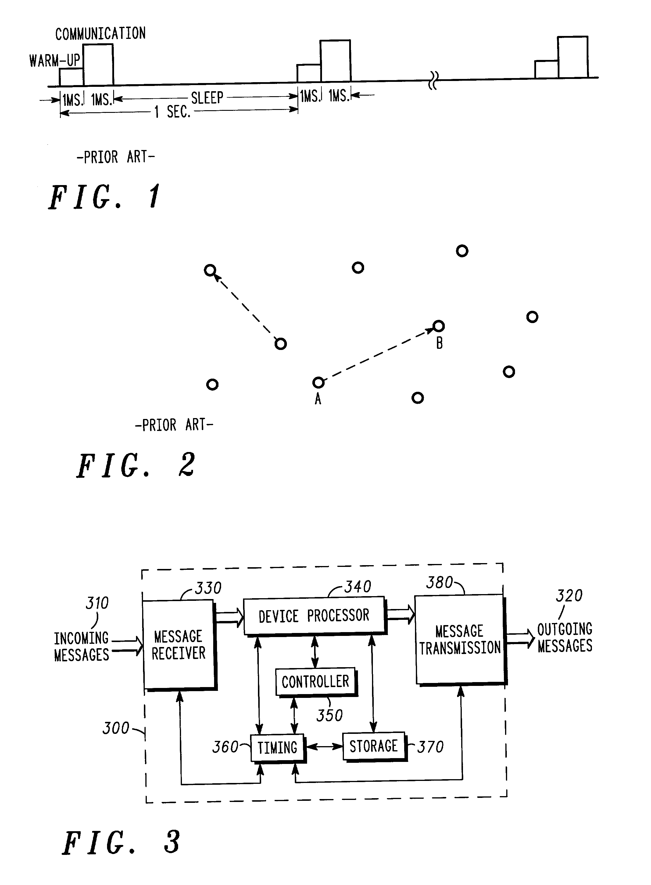
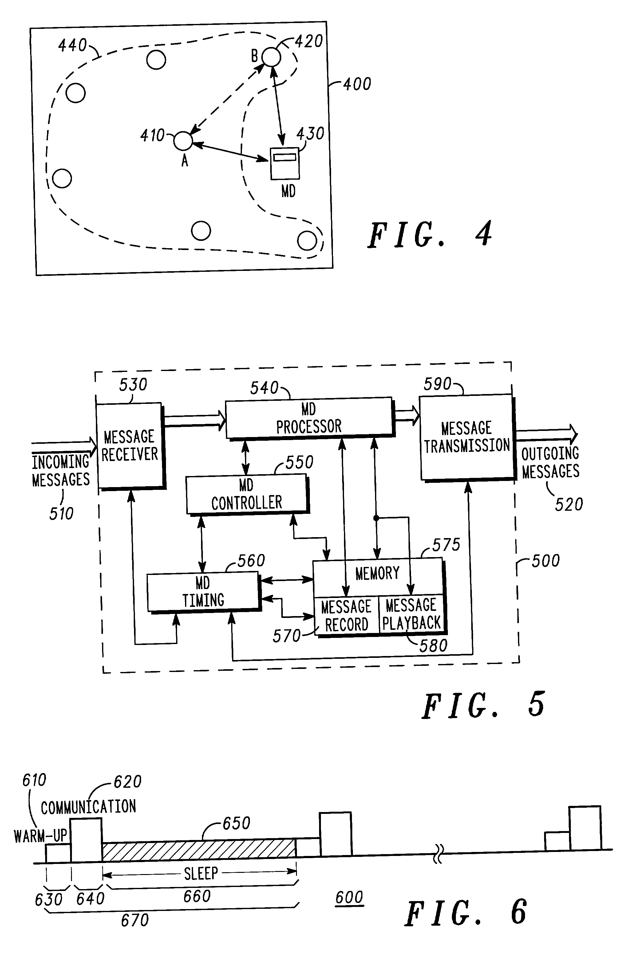
[0039] The present invention discloses a method and structure for a low power consumption protocol for low power wireless devices attached to an asynchronous network. Referring to FIG. 4, a simplified representation of a network 400 containing a plethora 440 of low power communication devices 410 and a dedicated MD 430 is shown, according to the present invention. Each of the low power communication devices 410 of network 400 has a low communication duty cycle and must therefore rely upon dedicated MD 430 for reliable communication. Dedicated MD 430 has a high communication duty cycle in comparison to the non-MD low power devices 410, and can store messages destined for any of low power wireless devices 410 within the group 440.

[0040] Referring now to FIG. 5, a system level block diagram 500 of the internal operation of a dedicated MD device 430 is shown. The dedicated MD device 430 is capable of sending and receiving several types of messages, including the source communication dev...

second embodiment

[0046] Instead of using dedicated MD 930, the functionality of a MD may be coupled to each of the plethora 440 of low power communication devices. Referring now to FIG. 13, a network 1300 containing a plethora of low power communication devices is shown, according to the present invention. Each low power communication device of the low power communication devices can function as MD. In FIG. 13, low power communication device 1330 is functioning as a MD. Note that low power communication device 1330 is not a dedicated MD 930. The low power communication device of the low power communication devices that will function as MD is selected at random.

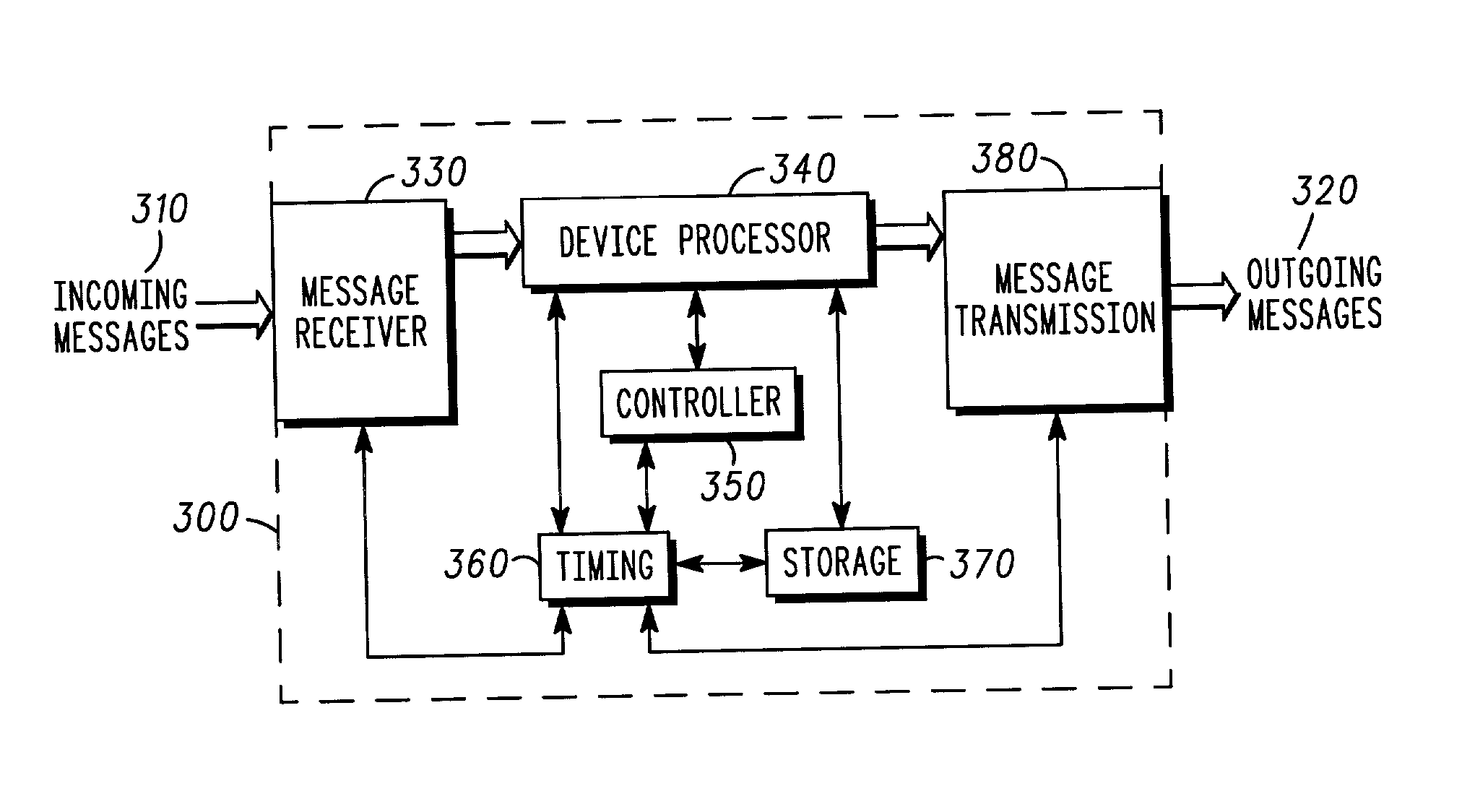
[0047] There are several approaches that may be used to select the next MD. The MD could be selected at random when the low power communications device acting as MD is not able to act as MD any longer. If each MD uses a randomly generated initial phase offset t0, then the distribution of MD functionality across the low power communication devi...

third embodiment

[0059] Referring to FIG. 23, a multiple access scheme in which N communication devices 2310 are in the network, according to the present invention. Each communication device of the N communication devices is constrained to receive and transmit information within a window 2320 of duration Tw seconds. Duration Tw is selected from the size of the network as determined by the number of communication devices in the network.

[0060] For example, for a network with five communication devices operating within a t1 period of 1000 seconds, the average latency is 200 seconds. If the communication cycle t1 is reduced to 300 seconds, the average latency is reduced by a factor of three. If the duration Tw of window 2320 is smaller than the communication period of the communication device, the duration of the communication period must be reduced to fit within window 2320. Reducing the duration of the communication period increases the likelihood of communication devices moving out of communication r...


PUM


Abstract

A low power consumption protocol for low power communication devices attached to an asynchronous network is described. In this protocol, a communication device is used as a high communication duty cycle Mediation Device (MD), thus permitting other communication devices to use a low communication duty cycle framing structure. The MD functions as a storage and retrieval service for messages between two devices when one device is not able to communicate. When the previously unavailable device becomes available, it can check in with the MD to retrieve any missed messages and respond to these messages accordingly. In a communication network, each of the low power communication devices can be configured to behave as MD's for a small amount of time. Sharing this responsibility among all communication devices in the network allows each device to maintain an low average communication duty cycle. This technique is applicable to a low power, low cost, zero-configuring, self-organizing, asynchronous network.

Description

CROSS REFERENCE TO RELATED APPLICATION[0001] This application is related to the applications entitled "System for Spread Spectrum Communication" (Docket No. CM003351J), "A Protocol for a Self-Organizing Network Using a Logical Spanning Tree Backbone" (Docket No. CM03403J), and "System for Code Division Multi-Access Communication" (Docket No. CM03333J) all filed on the same date as the present invention.FIELD OF THE INVENTION[0002] The present invention relates generally to communication networks and more specifically to the use of multiple access protocols in asynchronous communication networks.BACKGROUND OF THE INVENTION[0003] In communication networks, asynchronous transmission of information is often the technique used when communicating information between one or more communication devices within a communication network. Asynchronous transmission is often used when low power devices make up the network. These low power devices can use a low communication duty cycle frame structu...

Claims


Application Information

Patent Timeline
Patent Type & Authority Applications(United States)
IPC IPC(8): H04L12/56H04L29/08H04L29/00
CPCH04W4/12H04W48/08H04W84/18Y02D70/00H04W52/0219H04W76/10H04W88/04Y02D30/70H04W88/02H04W52/02H04W72/04
Inventor SHI, QICAIHUANG, JIANCALLAWAY, EDGAR H. JR.
Owner ARRIS ENTERPRISES LLC
Learn More