
Light transmission type image recognition device and image recognition sensor

a technology of image recognition and transmission type, applied in the field of light transmission type image recognition device and image recognition sensor, can solve the problems of inability to capture image devices having ccd, difficult to accurately recognize contours,

Inactive Publication Date: 2002-09-12
SANYO ELECTRIC CO LTD
View PDF8 Cites 13 Cited by
  • Summary
  • Abstract
  • Description
  • Claims
  • Application Information

AI Technical Summary

Benefits of technology

[0022] An example of the optical filter is an attenuation filter for reducing the optical density of light transmission. In this case, images which have different intensity variance are respectively input to the light transmission type image recognition devices.

Problems solved by technology

[1] It is impossible for image capturing devices having CCD (Charge Coupled Device) or CMOS (Complementary Metal-Oxide Semiconductor) as a basis and image recognition sensors using a technique for fabricating the image capturing devices as a basis to transmit light due to the limits of materials therefor.
), and the contour itself is difficult to accurately recognize.

Method used


Image

  • Light transmission type image recognition device and image recognition sensor
  • Light transmission type image recognition device and image recognition sensor
  • Light transmission type image recognition device and image recognition sensor

Examples


Embodiment Construction

[0063] [A] Description of Embodiment Relating Light Transmission Type Image Recognition Device and Image Recognition Sensor

[0064] [1] Description of Construction of Light Transmission Type Image Recognition Device

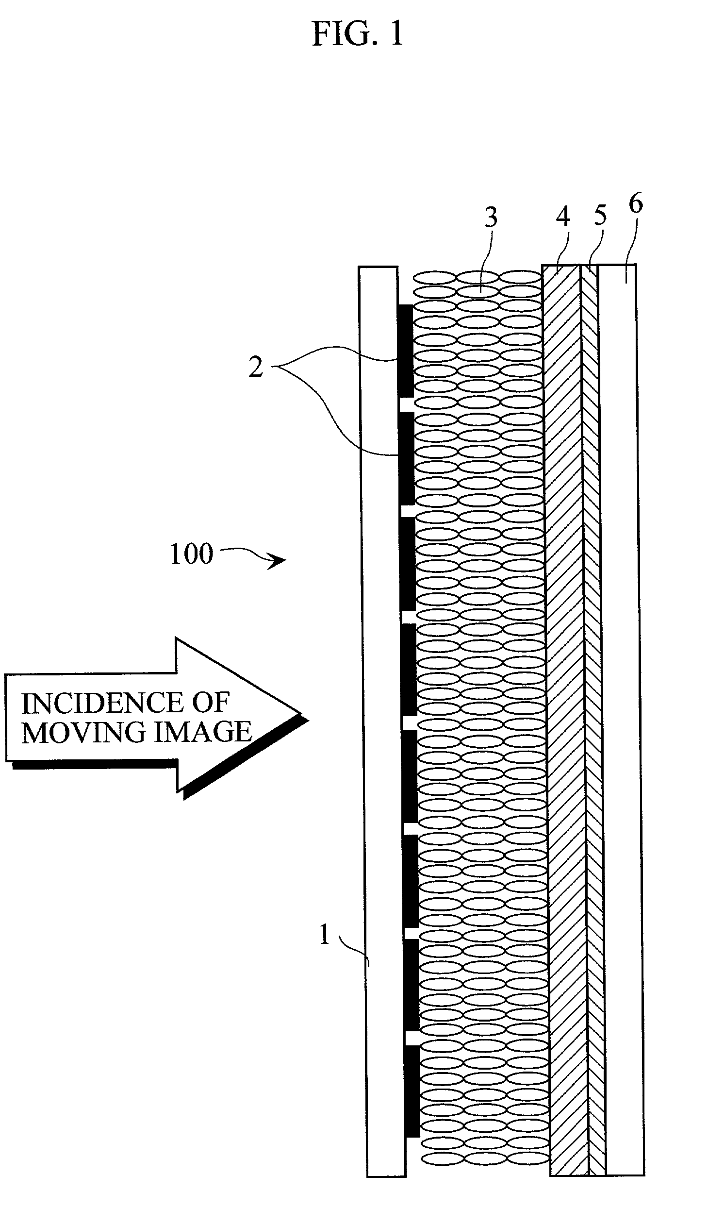
[0065] FIG. 1 illustrates the construction of a light transmission type image recognition device.

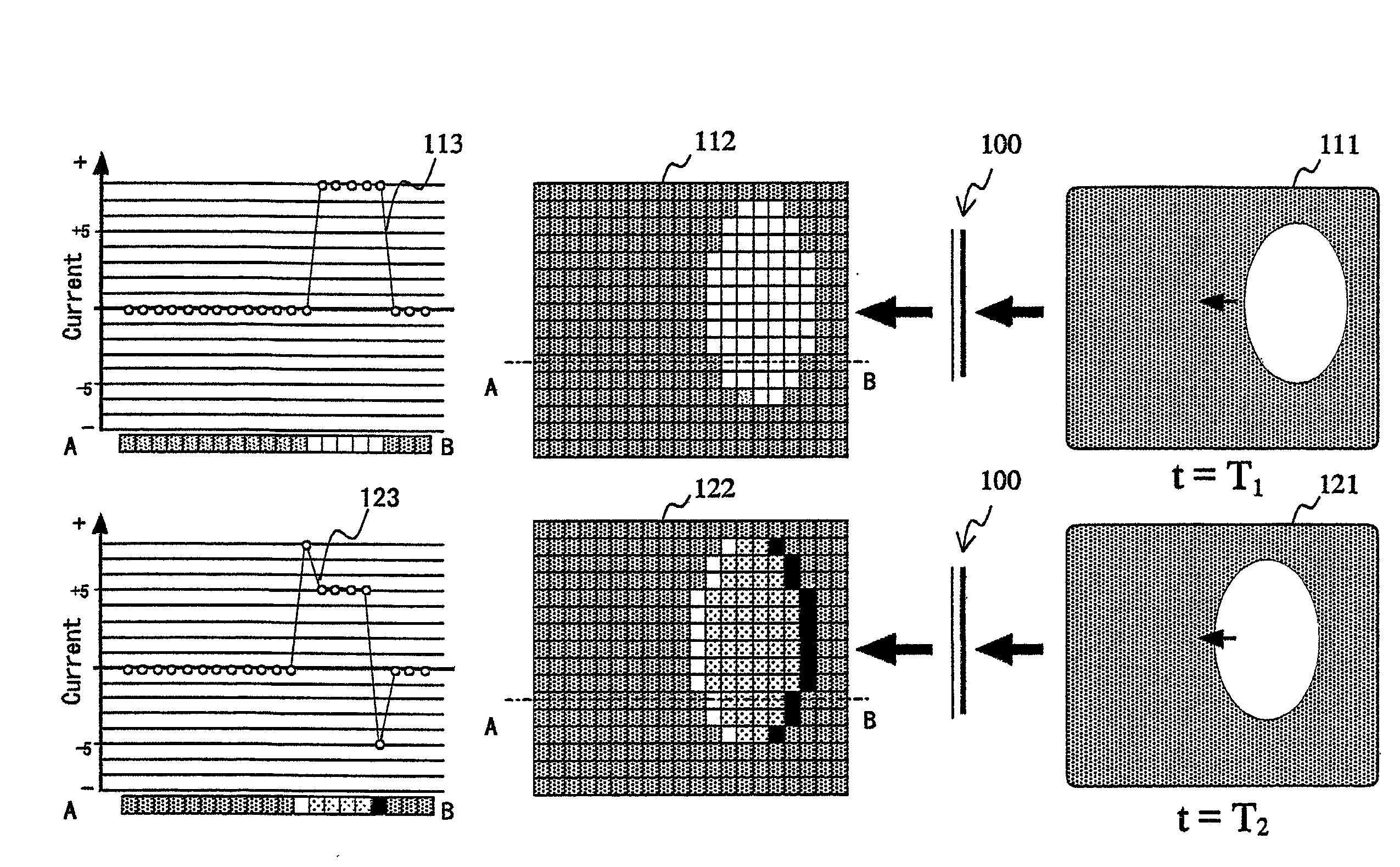
[0066] The light transmission type image recognition device 100 comprises a first substrate 1 having pixel electrodes 2 formed in a two-dimensional array on its surface, a second substrate 6 having a faced electrode 5 formed on its surface, and a visual pigment similar protein oriented film layer 3 and a transparent electrical insulating layer 4 which are arranged between both the electrodes. The visual pigment similar protein oriented film layer 3 is formed on the side of the pixel electrodes 2, and the electrical insulating layer 4 is formed on the side of the faced electrode 5.

[0067] In the light transmission type image recognition device 100, a moving object image may be pro...


PUM


Abstract

A light transmission type image recognition device comprises a first transparent substrate having a plurality of transparent pixel electrodes formed in a two-dimensional array on its surface, a second transparent substrate having a transparent faced electrode formed on its surface, and a visual pigment similar protein oriented film layer and a transparent insulating layer which are arranged between both the electrodes.

Description

BACKGROUND OF THE INVENTION[0001] 1. Field of the Invention[0002] The present invention relates to a light transmission type image recognition device using a visual pigment similar protein and an image recognition sensor.[0003] Furthermore, the present invention relates to a contour detecting apparatus and method for detecting the contour of a moving object at high speed on the basis of an image recognition device using a visual pigment similar photoelectric protein and a moving object region detecting apparatus and method for detecting a moving object region at high speed on the basis of an image recognition device using a visual pigment similar photoelectric protein.[0004] 2. Description of the Prior Art[0005] [1] It is impossible for image capturing devices having CCD (Charge Coupled Device) or CMOS (Complementary Metal-Oxide Semiconductor) as a basis and image recognition sensors using a technique for fabricating the image capturing devices as a basis to transmit light due to th...

Claims


Application Information

Patent Timeline
Patent Type & Authority Applications(United States)
IPC IPC(8): G06V10/88
CPCG06K9/74G06V10/88
Inventor SUGIYAMA, YUKIHIROSUGIMOTO, KAZUHIDE
Owner SANYO ELECTRIC CO LTD
Learn More