Front load pressure jacket system with syringe holder

a pressure jacket and front load technology, applied in the field of pressure jacket systems, can solve the problems of fluid spillage, fluid spillage, air from the syringe may get inside the pressure jacket, etc., and achieve the effect of preventing fluid spillage, preventing fluid spillage, and preventing fluid from entering the pressure jack

Inactive Publication Date: 2002-09-12
MEDRAD INC.
View PDF0 Cites 36 Cited by
  • Summary
  • Abstract
  • Description
  • Claims
  • Application Information

AI Technical Summary

Benefits of technology

[0013] A fifth embodiment of the present invention includes a pressure jacket with a jacket cylinder having an open front end and a rear end coupled to the injector head. A first pivot is coupled to the injector head and a first tie rod is attached to the first pivot. A second pivot is coupled to the injector head and a second tie rod is attached to the second pivot. A front retaining plate joining the front ends of the tie rods allows the retaining plate to be pivotable between a closed position for holding the syringe within the jacket cylinder and an open position to allow the insertion or removal of the syringe from the jacket cylinder.

Problems solved by technology

However such an arrangement causes a problem when the syringe is removed from the pressure jacket.
This requires the patient fluid path to be disconnected which presents a potential biohazard and may result in spilling fluids onto the pressure jacket.
Additionally, fluid spilled during loading and purging air from the syringe may get inside the pressure jacket and require cleaning.

Method used


Image

  • Front load pressure jacket system with syringe holder
  • Front load pressure jacket system with syringe holder
  • Front load pressure jacket system with syringe holder

Examples


first embodiment

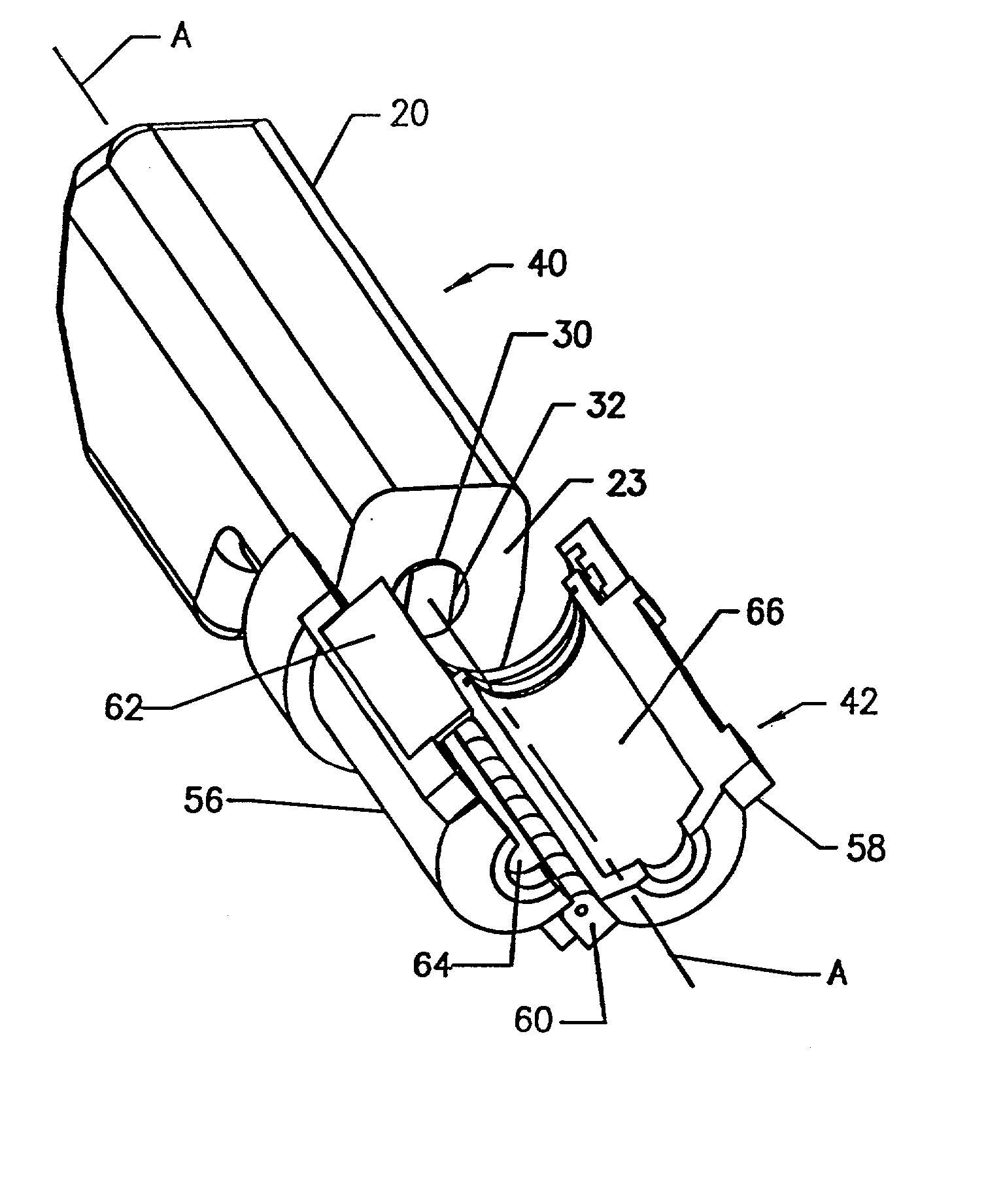
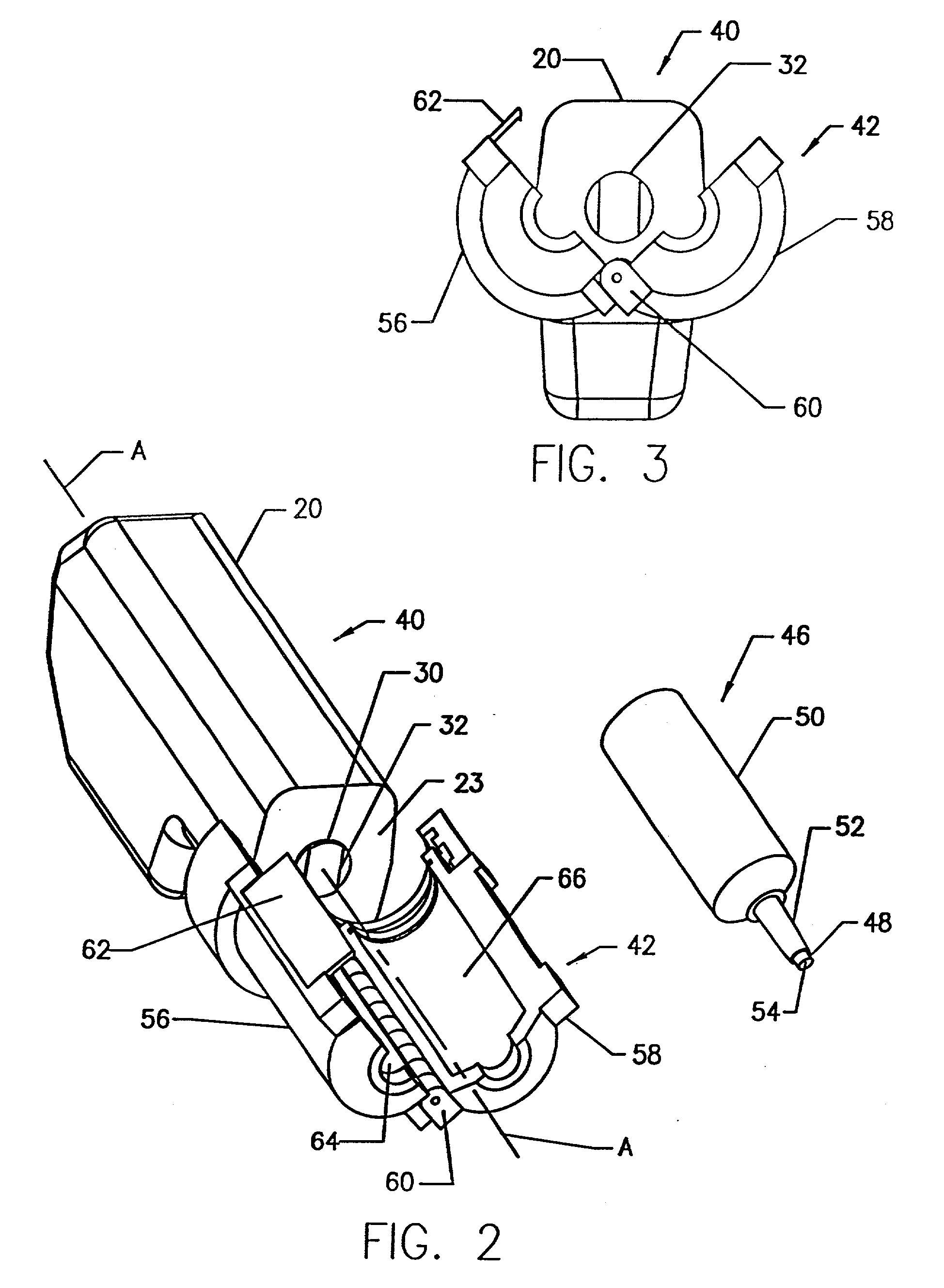
[0040] As shown in FIGS. 2-5, the present invention allows front loading and removal of syringe 46 and any tubes attached thereto while minimizing fluid spills. Further, as syringe 46 is retained within pressure jacket 42, the amount of material required to manufacture syringe 42 is reduced because the pressure jacket 42, instead of the syringe walls, bears the majority of the pressure force exerted during a fluid injection procedure.

second embodiment

[0041] the present invention is shown in FIGS. 6 and 7. FIG. 6 shows a fluid injector 70 having a pressure jacket system 72 in an open position which permits the loading and removal of a syringe 76. Pressure jacket 72, a generally "alligator jaw" type, is hingedly affixed to an injector head 20 to which syringe 76 may be releasably installed. Specifically, as shown in FIG. 7, syringe 76 is held by a combination of a first or top jacket half 78 and a second or bottom jacket half 80, together forming pressure jacket 72, and a locking ring 82. Both top jacket half 78 and bottom jacket half 80 are preferably made of clear plastic and have a semi-cylindrical shape. Interior semi-cylindrical surfaces 84 and 86 of top and bottom jacket halves 78 and 80, respectively, conform to the exterior surface of the body of the syringe 76. Jacket halves 78 and 80 have respective rear ends 88 and 90 located near the injector front face 23 and front ends 92 and 94 which coact to form an opening for the...

third embodiment

[0043] FIGS. 8-11 show the present invention. A fluid injector indicated generally at 110 includes a pressure jacket 112 with a plurality of locking fingers 114 for engaging a syringe 116, shown in an open position in FIG. 10 and a closed position in FIG. 11. Pressure jacket 112 is connected at its rear end 132 to injector head 20 by any suitable means, such as a threaded connection (not shown). Syringe 116 has a cylindrical body 118 having a front end 120 and an open rear end 122. The front end 120 of syringe 116 is tapered and connected to a neck 124. A disk shaped drip flange 126 is formed around the neck 124.

[0044] The pressure jacket 112 includes a hollow cylinder 128 which is preferably made of clear plastic. A distal end 130 of the cylinder 128 is open to allow loading and removal of the syringe 116. The distal end 130 of pressure jacket 112 has an outside surface 134 which is slightly smaller in diameter than that of cylinder 128. The outside surface 134 of the distal end 13...


PUM


Abstract

The pressure jacket systems of the invention are used to permit the front loading and removal of a syringe from an injector and include a first jacket segment and a second jacket segment surrounding the exterior surface of the syringe, interior surfaces comformable to the exterior surface of the syringe, a mechanism which allows movement of the first jacket segment in relation to the second jacket segment to permit insertion and removal of the syringe from the pressure jacket, and a mechanism for securing the first and second jacket segments in a fixed relationship upon insertion of the syringe.

Description

TECHNICAL FIELD OF THE INVENTION[0001] This invention relates to pressure jacket systems for securing a syringe in an injector head. More specifically, the invention relates to pressure jacket systems which allow front loading and removal of a syringe, and which hold the syringe securely to an injector head during injection procedures.BACKGROUND OF INVENTION[0002] In the medical field, patients often are injected with fluids in procedures such as angiography. In such procedures, which require controlled injection of a large volume of fluid into a patient, a needle is used as a conduit for the fluid which is connected to the syringe by a connector tube. The syringe is mounted on a motorized injector having an injector head.[0003] For long term compatibility with injectable fluids, syringes may be made of polypropylene with a minimum wall thickness. The thickness is critical as typical pressures of up to 1200 p.s.i. are used to inject the fluids into a patient. For safety and sanitary...

Claims


Application Information

Patent Timeline
Patent Type & Authority Applications(United States)
IPC IPC(8): A61M5/145A61M5/142A61M37/00B05C17/01
CPCA61M5/14546A61M5/14566A61M2005/14553B05C17/01Y10S128/01B05C17/00596A61M5/145
Inventor REILLY, DAVID M.UBER, ARTHUR E. IIIHIRSCHMAN, ALAN D.GELBLUM, EUGENE A.
Owner MEDRAD INC.
Why Eureka
Try Eureka