Method and apparatus for compacting molding sand

a technology of compacting molding and sand, which is applied in the direction of manufacturing tools, moulding machines,foundry moulding apparatus, etc., can solve the problems of difficult to make small sandmold draft, inability to easily change the conditions of compaction, and inability to stably separate a produced sandmold from the pattern plate, etc., to achieve the effect of enhancing the effect of invention and increasing the pressure of secondary compacting

Inactive Publication Date: 2002-09-19
SINTOKOGIO LTD
View PDF0 Cites 16 Cited by
  • Summary
  • Abstract
  • Description
  • Claims
  • Application Information

AI Technical Summary

Benefits of technology

0009] In this invention the term "frame member" denotes a flask when a mold to be produced is a mold held in a flask, or a molding frame when a mold to be produced is a flaskless mold. Further, a "mold" to be produced includes a mold held in a flask and a flaskless mold, which has been removed from a molding frame after it had been solidified in the molding frame. Further, the pressure for secondarily compacting the molding sand may be equal to that for primarily compacting the molding sand. However, a higher pressure in secondary compacting than in primary compacting would enhance the effect of the invention. Further, in this invention the compacting means may be any type of a single member to compact molding sand, a plurality of members to compact molding sand, such members being provided with flexible sheets on which pressurized air is applied, etc. Further, after the step of adjusting the volume of the mold space, the molding sand may be fed into the mold space. By this, the conditions for the compaction can be readily determined in accordance with the change in the molding sand

Problems solved by technology

This produces a problem in that, for example, a pit must be provided in a floor when the machine is installed on it.
Further, separating a produced sandmold from the pattern plate cannot be done stably.
Thus it is difficult to make smaller the draft of the sandmold.
Further, even when the properties of the molding sand are changed, the conditions for the compaction cannot be readily changed.

Method used


Image

  • Method and apparatus for compacting molding sand
  • Method and apparatus for compacting molding sand
  • Method and apparatus for compacting molding sand

Examples


first embodiment

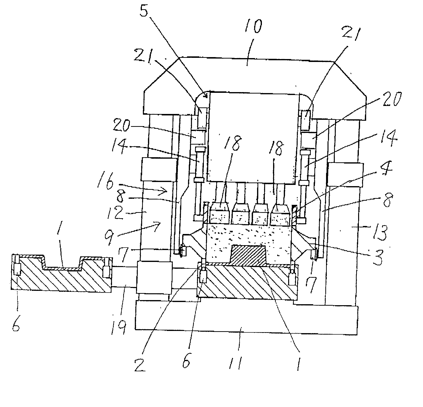
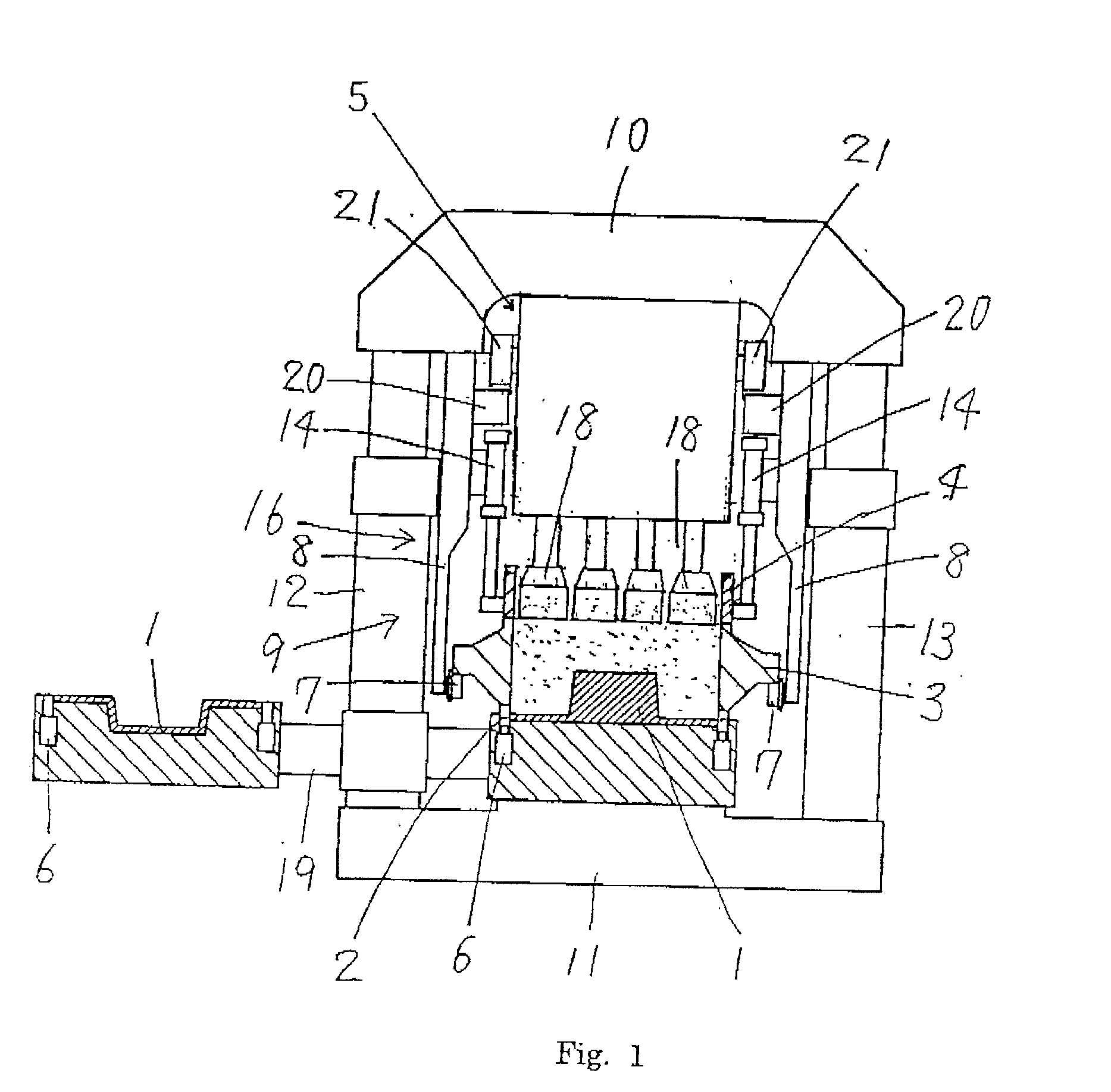
[0022] a molding machine that implements the present invention is now explained by reference to FIG. 1. The molding machine comprises a pattern plate 1, which is fixed in a horizontal position, a leveling frame 2 disposed for vertical sliding movement around the outer periphery of the pattern plate 1., a flask 3, as a frame member, disposed for vertical movement above the leveling frame 2, a filling frame 4 disposed for vertical movement above the flask 3, and compacting means 5 having a lower part that can enter the filling frame 4.

[0023] The pattern plate 1, which includes a pattern, is secured to the top of a pattern plate carrier 19a of a pattern plate changer 19 (below explained). If necessary, the pattern plate 1 may be provided with vent holes (not shown) embedded in its top surface, depending on the shape of the pattern. The leveling frame 2 is embedded in the pattern plate carrier 19a such that it is vertically moved by a plurality of hydraulic cylinders 6, which are also e...

second embodiment

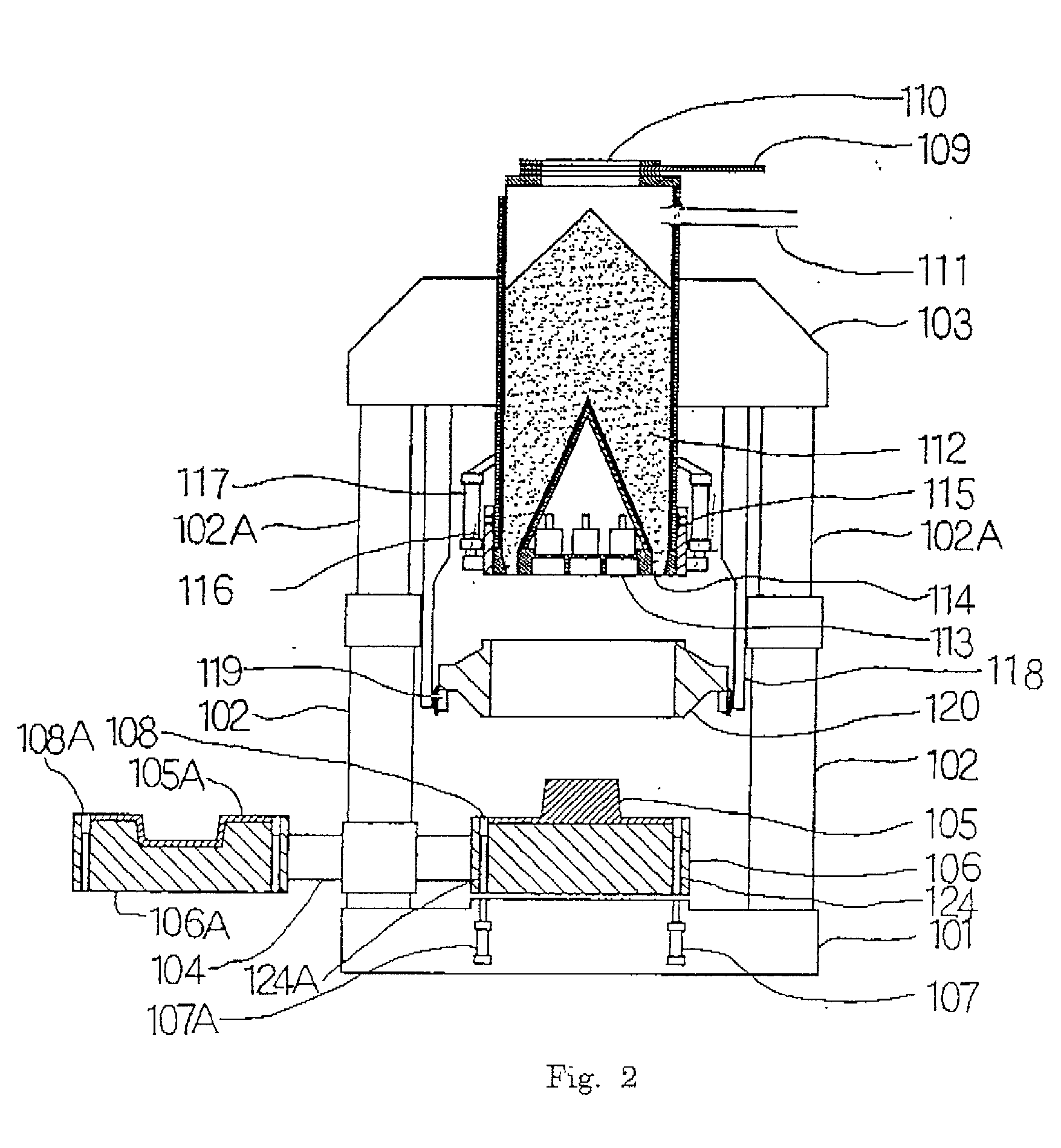
[0030] the molding machine that implements the method of the invention is now explained by reference to FIGS. 2-10.

[0031] In FIG. 2 a pair of upwardly-facing frame-setting cylinders 102, 102 are mounted on a base 101 of the machine. A supporting frame 103 bridges the distal ends of the piston rods 102A. 102A of the frame-setting cylinders 102, 102. The frame-setting cylinders are configured to face upwardly such that they retract toward the base.

[0032] A pattern plate changer 104 is rotatably mounted at its mid portion on one of the frame-setting cylinders 102, 102 (the left one in FIG. 2) such that it can rotate in a horizontal plane. The pattern plate changer 104 carries, at both its ends, pattern plate carriers 106, 106A, which are alternately placed on the central part of the base 1 when the pattern plate changer 104 rotates. The base 1 has springs (not shown) on its top surface so that the carrier 106 or 106A is placed on the base 1 through the springs with the bottom of the ca...


PUM

PropertyMeasurementUnit
heightaaaaaaaaaa
heightaaaaaaaaaa
heightaaaaaaaaaa

Abstract

A method for compacting molding sand in a mold space defined by a pattern plate, which is fixed in a horizontal position when the molding sand is compacted, a leveling frame disposed for vertical sliding movement around the outer periphery of the pattern plate, a frame member disposed for vertical movement above the leveling frame, and a filling frame disposed for vertical movement above the frame member. The method comprises the steps of feeding molding sand into the mold space, primarily compacting the molding sand in the mold space from above by compacting means while at least the leveling frame is being set so that it cannot be lowered, and secondarily compacting the molding sand in the mold space from above by the compacting means while the leveling frame, the frame member, and the filling frame are set so that these elements can be lowered.

Description

FIELD OF THE INVENTION[0001] This intention relates to a method and an apparatus for compacting molding sand.DESCRIPTION OF THE PRIOR ART[0002] In one conventional method of compacting molding sand that has been charged into a mold space defined by a pattern plate and a flask, means for compacting the molding sand and the pattern plate are moved relative to each other. In this method a molding machine requires a large hydraulic cylinder for vertically moving the pattern plate, and hence has a high profile. This produces a problem in that, for example, a pit must be provided in a floor when the machine is installed on it. Further, separating a produced sandmold from the pattern plate cannot be done stably. Thus it is difficult to make smaller the draft of the sandmold. A great draft would make a sandmold heavy. Certainly, this is not preferable. Further, even when the properties of the molding sand are changed, the conditions for the compaction cannot be readily changed.[0003] This i...

Claims


Application Information

Patent Timeline
Patent Type & Authority Applications(United States)
IPC IPC(8): B22C15/02B22C19/04
CPCB22C15/02B22C19/04B22C15/08
Inventor KANETO, KIMIKAZUHIRATA, MINORUHADANO, YUTAKASAKAI, TSUYOSHI
Owner SINTOKOGIO LTD
Why Eureka
Try Eureka