Adhesive roller construction

a technology of adhesive rollers and adhesive strips, applied in the field of adhesive rollers, can solve the problems of waste of adhesive rolls, difficulty in accurately identifying users, and the inability to use adhesive rolls, and achieve the effect of reducing or eliminating the stress on the strip

Inactive Publication Date: 2002-10-10
HELMAC PROD CORP
View PDF0 Cites 35 Cited by
  • Summary
  • Abstract
  • Description
  • Claims
  • Application Information

AI Technical Summary

Benefits of technology

0011] At least one elongated perforation, which may be a continuous slit, is formed in the roll so that the perforation extends through the multiple layers of the strip. Unlike the previously known adhesive roller constructions, however, this perforation extends diagonally from a position spaced inwardly from at least one side ...

Problems solved by technology

One disadvantage of the previously known lint rollers having a continuous strip is that it is very difficult, if not altogether impossible, for the user to accurately remove a portion of the used strip equal to substantially one revolution of the adhesive roll.
Removal of more than one revolution of the strip from the adhesive roll results in waste of the adhesive roll since the excess strip removed is never used.
Conversely, the removal of a strip substantially less than one full revolution of the adhesive roll results in used adhesive being left on the roll after the portion of the strip has been removed.
The used adhesive, if a significant portion of the exposed area of the roll, results in unsatisfactory detritus removal for the adhesive roll.
These previous...

Method used


Image

  • Adhesive roller construction
  • Adhesive roller construction

Examples


Embodiment Construction

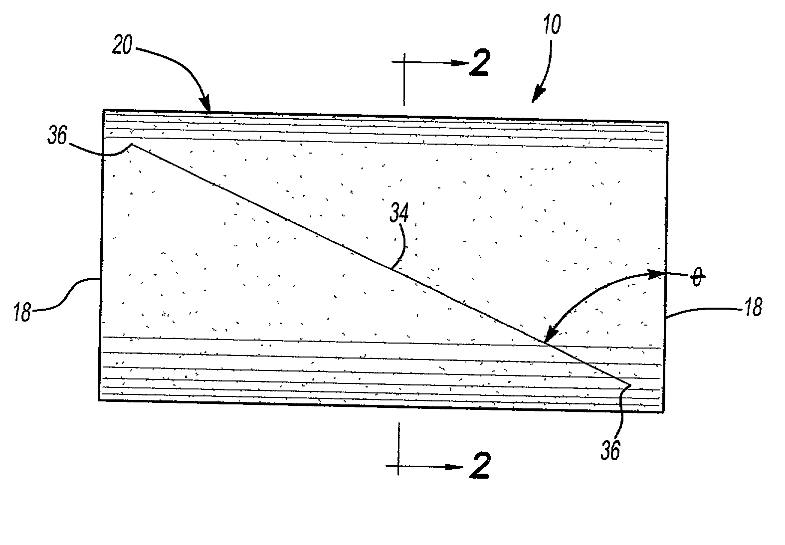
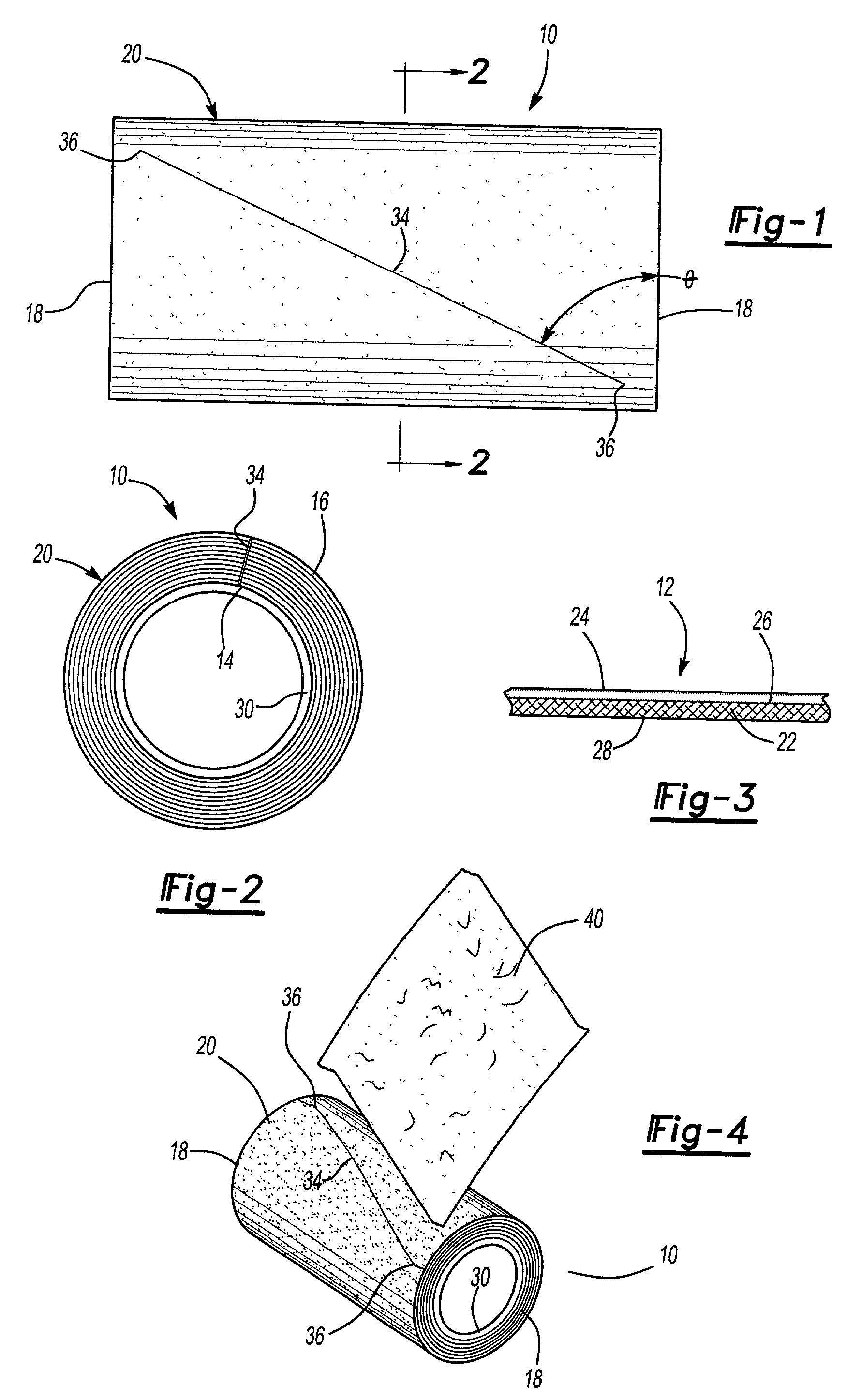
[0018] With reference first to FIGS. 1-3, a preferred embodiment of the adhesive roll construction 10 is there shown and comprises an elongated strip 12 having a first end 14 (FIG. 2), a second end 16 (FIG. 2) and a pair of spaced and substantially parallel sides 18. The strip is wound from the first end 14 and to the second end 16 into a tubular cylindrical roll 20 in which multiple layers of the strip 12 overlap each other.

[0019] As best shown in FIG. 3, the strip 12 comprises a backing layer 22 and an adhesive layer 24 on one side 26 of the backing layer 22. Preferably, the adhesive layer 24 overlies the entire side 26 of the backing layer 22 so that, when the strip 22 is wound into the cylindrical roll 20, the adhesive layers 24 adhesively, but detachably, engage the opposite side 28 of the backing layer 22 of the next outer layer of the strip 22 on the adhesive roll 20.

[0020] With reference now particularly to FIG. 2, the adhesive roller construction 10 preferably includes a tu...


PUM


Abstract

An adhesive roller construction is disclosed having an elongated strip. The strip includes both a backing layer and an adhesive layer overlying one side of the backing layer. The strip has a first end, a second end and two spaced apart sides. The strip is wound from its first end to its second end into a tubular cylindrical roll in which multiple layers of the strip overlap each other. At least one elongated perforation is formed in the roll so that the perforation extends through the multiple layers of the strip. Furthermore, this perforation extends diagonally from a position spaced inwardly from one side of the strip to a position spaced inwardly from the opposite side of the strip. Optionally, the perforation extends to one or both sides of the strip.

Description

[0001] I. Field of the Invention[0002] The present invention relates generally to adhesive rollers and, more particularly, to such a roller used for detritus removal.[0003] II. Description of the Prior Art[0004] Lint rollers have long been known and widely used for removing detritus, such as pet hair, dandruff, lint and the like from clothing, furniture, etc. These previously known lint rollers typically comprise a handle having a tubular and cylindrical tape roll rotatably mounted to the handle.[0005] Many previously known adhesive rolls for detritus removal consist of a continuous strip having a backing and with an adhesive provided on one side of the backing. The strip is wound into a tubular cylindrical roll so that the strip overlaps itself to form multiple layers. As the adhesive becomes depleted from use, a portion of the strip is torn away from the roll to expose fresh adhesive. This process continues until the entire roll has been depleted at which time a new roll is mounte...

Claims


Application Information

Patent Timeline
IPC IPC(8): A47L25/00
CPCY10T428/15A47L25/005
Inventor MCKAY, NICHOLAS D. JR.
Owner HELMAC PROD CORP
Why Eureka
Try Eureka