Double clutch assembly

a technology of clutch assembly and clutch body, which is applied in the direction of clutches, road transport, climate sustainability, etc., can solve the problem of relative complexity of design

Inactive Publication Date: 2002-10-10
ZF FRIEDRICHSHAFEN AG
View PDF0 Cites 17 Cited by
  • Summary
  • Abstract
  • Description
  • Claims
  • Application Information

AI Technical Summary

Benefits of technology

[0008] According to the invention, therefore, the principle of providing a separate engaging / disengaging mechanism for each clutch area, these separate mechanisms then also being actuated separately, is abandoned. Instead, a single mechanism of this type is provided, which, depending on how it is actuated, can have the effect either of engaging one of the clutch areas while disengaging the other or of keeping both clutch areas in a state of partial torque transmission. This considerably simplifies both the design of a clutch assembly of this type and the measures required to actuate the clutch.
[0014] To minimize the actuation effort required to actuate the clutch assembly and to shift from one of the clutch areas to the other, the double clutch assembly according to the invention is provided with a force storage unit, by means of which one of the clutch areas is kept pretensioned in its torque-transmitting state.
[0017] The effort required to construct the clutch assembly and to actuate it to execute the various engagements and disengagements can be further simplified by providing the engaging force-transmission component with a second force storage element, which has an area which cooperates with the first force storage element, this area of the second component being pretensioned in the direction toward the pressure plate of one of the clutch areas. By keeping one of the clutch areas pretensioned in its torque-transmitting state, the only measure which must be taken to switch from the one clutch area to the other is to generate an actuating force in a single direction, whereas shifting back in the other direction can be accomplished simply by ceasing to generate this force.
[0018] To simplify the design even further, the first force storage element is permanently connected to the second force storage element, the two preferably being designed as a single unit. This can be realized, for example, by designing the first force storage element with a plurality of force storage sections projecting from the second force storage element toward the pressure plate of one of the clutch areas.

Problems solved by technology

This leads to a relatively complicated design, however, because the two engaging / disengaging mechanisms, such as engaging / disengaging piston-cylinder assemblies, must be installed in a small space and thus staggered radially with respect to each other.

Method used


Image

  • Double clutch assembly
  • Double clutch assembly
  • Double clutch assembly

Examples


Embodiment Construction

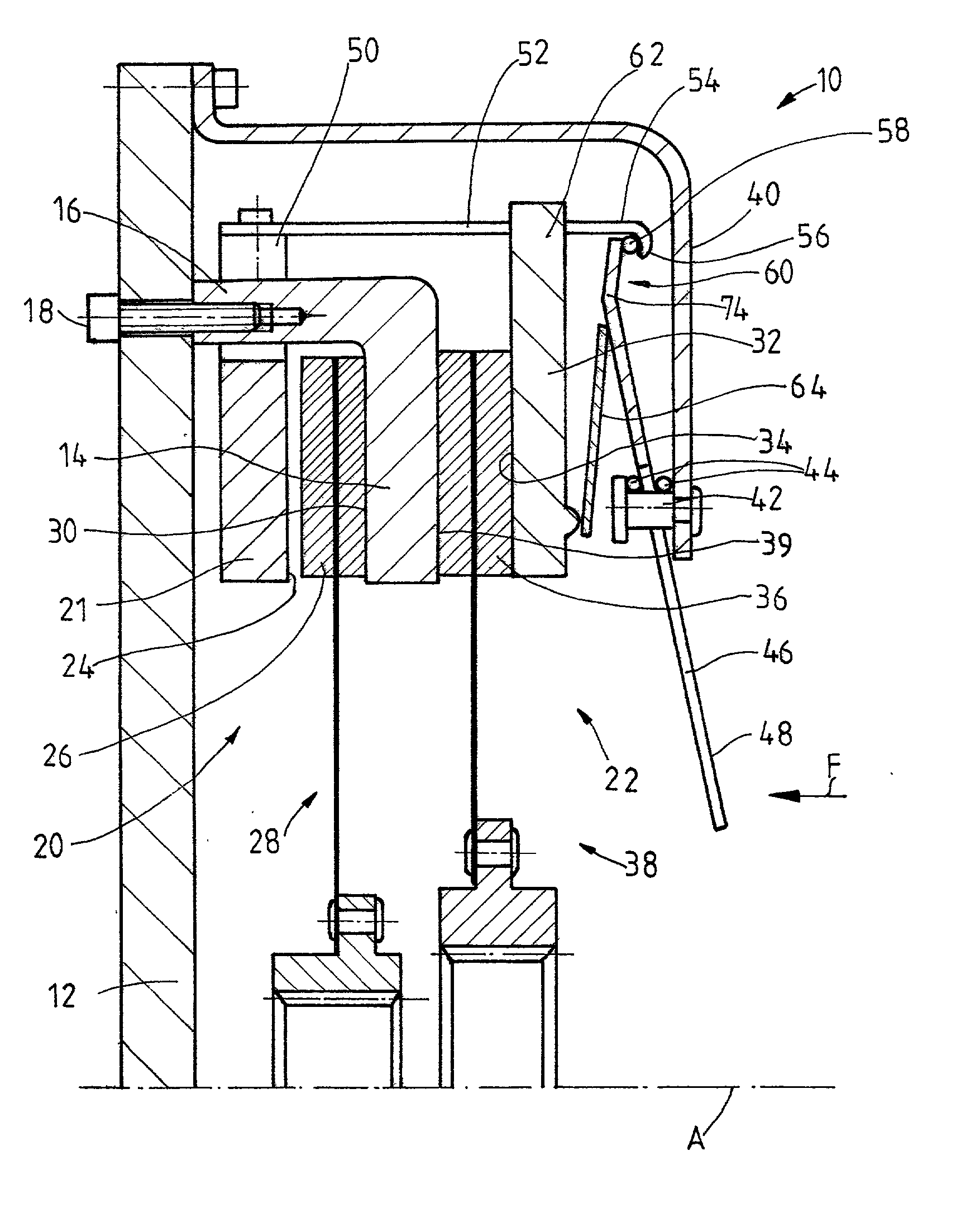
[0029] In FIG. 1, a double clutch assembly 10 includes a flywheel 12, which can be or is connected to a drive shaft (not shown) such as a crankshaft, for rotation in common with the shaft. In its radially outer area, an intermediate disk element 14 is rigidly connected to the flywheel 12; the cylindrical section 16 of this disk element is bolted by a plurality of threaded bolts 18 or the like to the flywheel 12. The intermediate disk element 14 works together equally with the two different clutch areas 20, 22 of the double clutch assembly 10.

[0030] The first clutch area 20 comprises a first pressure plate 21, the first friction surface 24 of which can be pressed against friction linings 26 of a clutch disk 28 of the first clutch area 20. When this happens, the friction linings 26 of the clutch disk 28 are pressed against a second friction surface 30 of the first clutch area 20, located on the intermediate disk element 14.

[0031] The double clutch assembly 10 also includes a second pr...


PUM


Abstract

A first clutch area produces a first torque-transmitting connection between a drive element and a first driven element, and a second clutch area produces a second torque-transmitting connection between the drive element and a second driven element. A common engaging / disengaging mechanism actuates the first clutch area and the second clutch area to produce and to nullify the first and second torque-transmitting connections.

Description

[0001] 1. Field of the Invention[0002] The present invention pertains to a double clutch assembly, comprising a first clutch area for the optional production of a first torque-transmitting connection between a drive element and a first driven element, and a second clutch area for the optional production of a second torque-transmitting connection between the drive element and a second driven element.[0003] 2. Description of the Related Art[0004] Double clutch assemblies of this type are used, for example, in conjunction with variable gear transmissions which have two transmission input shafts. Different gear stages can be engaged, depending on which of the transmission input shafts is in the torque-transmitting path after actuation of the associated clutch area. To implement the engagements and disengagements of the clutch, it is known in double clutch assemblies of this type that each clutch area can have its own, separate engaging / disengaging mechanism, so that, depending on the ac...

Claims


Application Information

Patent Timeline
Patent Type & Authority Applications(United States)
IPC IPC(8): F16D13/38F16D13/52F16D13/58F16D13/75F16D21/06
CPCF16D13/385F16D13/52F16D13/583F16D13/585Y02T10/76F16D21/06F16D2021/0607F16D2021/0676F16D2021/0684F16D13/757
Inventor DAU, ANDREASORLAMUNDER, ANDREASFELDHAUS, REINHARDRANDOW, JORGROLL, GERHARDSCHIERLING, BERNHARDPETERSEIM, MICHAELRANDOW, ANKE
Owner ZF FRIEDRICHSHAFEN AG
Why Eureka
Try Eureka