[0003] In the wiper blade according to the invention, with the characterizing features of claim 1, it is possible, starting from one end of the support element, to insert the wiper strip in a rectilinear fashion between the two opposing longitudinal edges of the spring strip, where their inner,
free edge strips protrude into the longitudinal grooves of the wiper strip. This simple installation movement can be easily executed by an automated installation
machine, which achieves a considerable cost reduction. In addition, the disadvantageous installation opening of the slot can be eliminated because the bridge-like crosspieces permit the rectilinear installation motion of the wiper strip from one end of the support element.
[0008] A stable, low-torsion support element is produced if at least one crosspiece is disposed at each end section of the two associated spring strips. Depending on the length of the wiper blade, however, it is also quite conceivable to connect the two spring strips to each other by means of additional bridge-like crosspieces. In short wiper blades, it has turn out that placing a single crosspiece at each end section of the support element is sufficient to achieve a stable, torsion-free wiper blade.
[0009] An additional stabilization of the support element is achieved if a crosspiece disposed in the
central region of the two associated spring strips is embodied as part of a connecting device for connecting the wiper blade to the wiper arm.
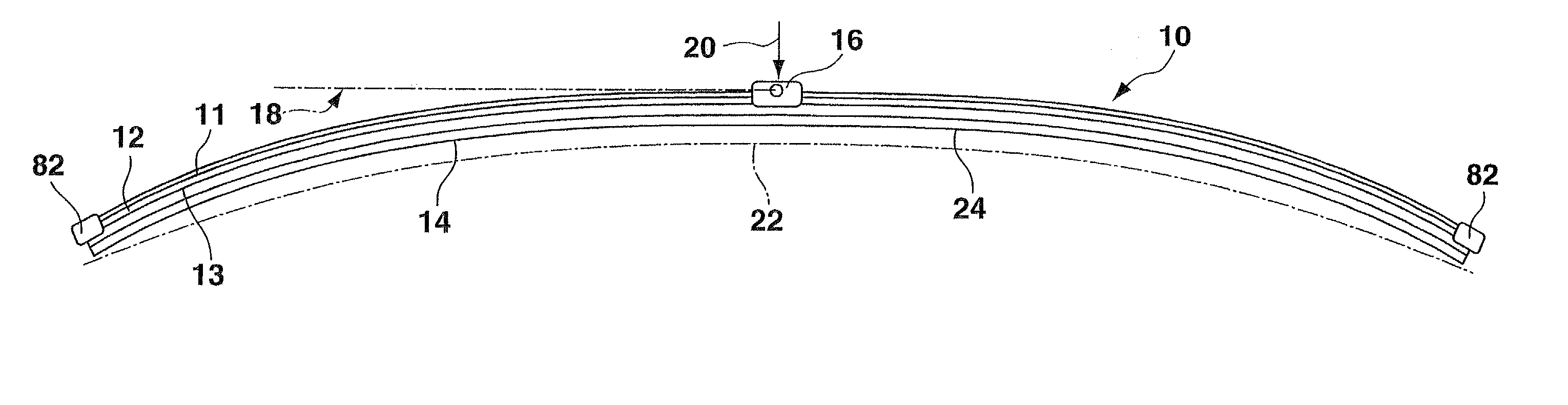
[0010] In a modification of the invention, at least one of the two crosspieces, which is respectively disposed at one of the end sections of the spring strips, has a stop, which is connected to its middle section and partially covers the end of the wiper strip adjacent to it. This prevents the wiper strip from creeping out of the support element in the longitudinal direction of the wiper blade.
[0011] When a crosspiece, which is provided with a stop, is respectively disposed at each of the two ends of the support element, the distance between the two stops is greater than the length of the wiper strip in order to assure a favorable
adaptation of the wiper strip to the respective window curvature.
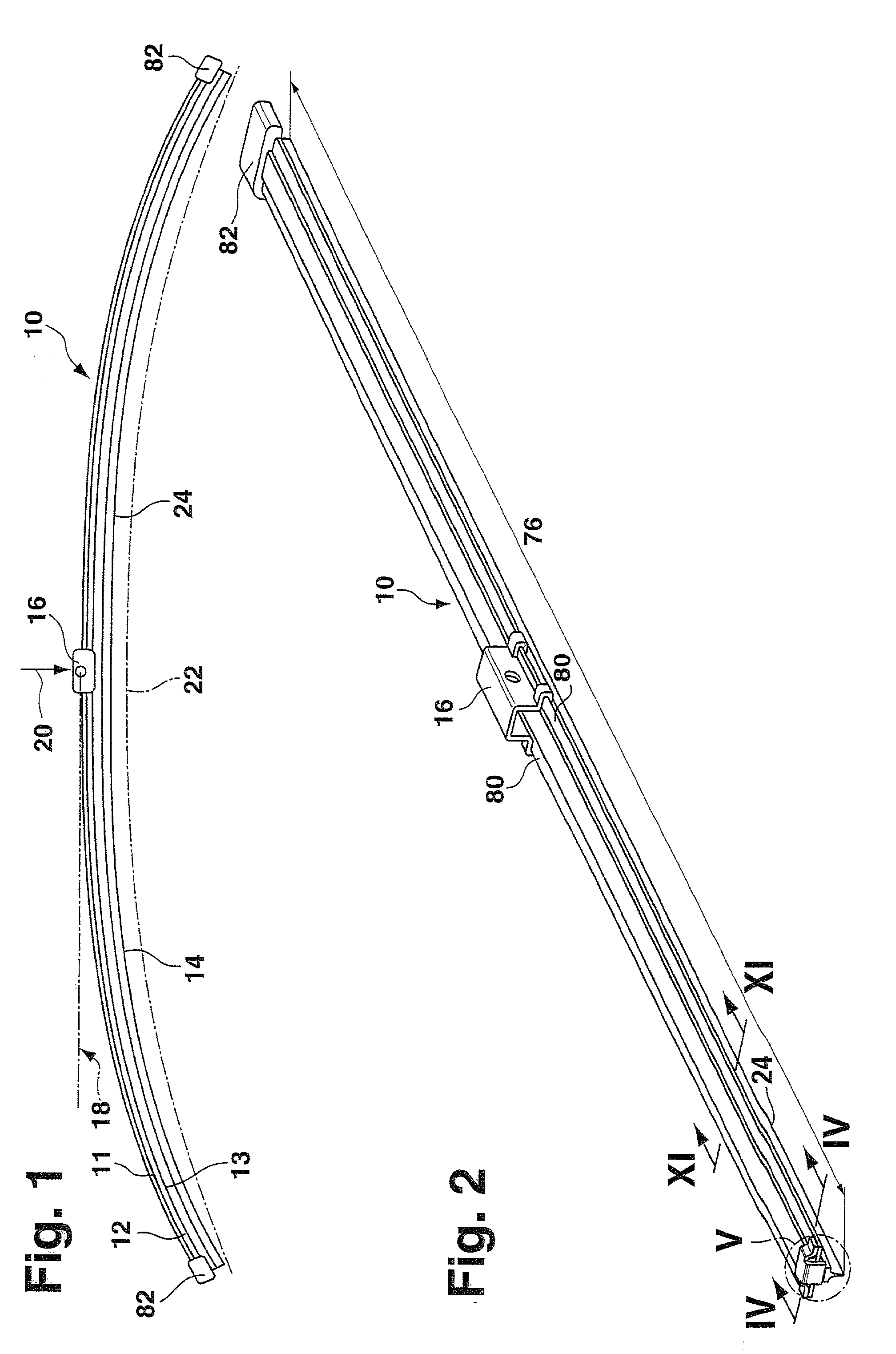
[0012] In order to reduce the danger of injury when manipulating the wiper, each crosspiece disposed at the end sections of the two spring strips is provided with a covering cap that is preferably made of plastic.
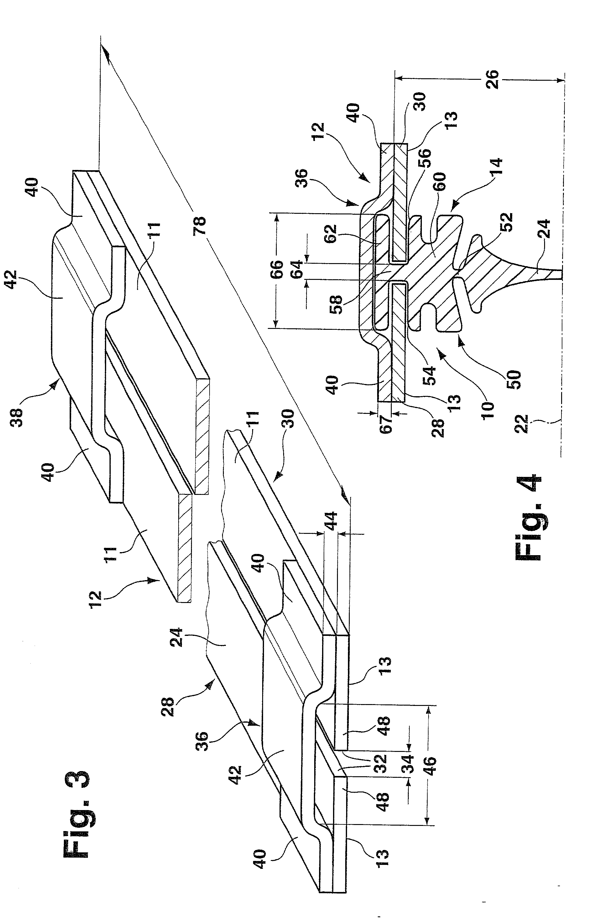
[0013] Other advantages during the wiping operation of the wiper according to the invention ensue from the fact that the thickness of a wall or intermediary strip between the two longitudinal grooves in the wiper strip is less than the distance between the adjacent longitudinal edges of the two associated spring strips. The longitudinal play of the wiper strip in the support element consequently produces a "free-floating", tension-free wiper strip that can continuously adapt to the window profile during wiper operation without being impaired by a clamped connection.
[0014] A particularly advantageous modification of the wiper blade is achieved if a wiper strip, which has a uniform cross section over its longitudinal span, has a strip-like wiper lip, which can be placed against the window and which, by means of a narrow intermediary strip that is formed by groove-like constrictions on opposite sides, is connected to a covering strip secured to the support element, and each of the two adjacent, inner longitudinal edges of the spring strips is disposed in one of the two groove-like constrictions of the wiper strip. This reduces the height of the wiper blade considerably. Because the width of the
constriction groove is greater than the thickness of the spring strips in a partial region, the wiper lip can always tilt into the required drag position during wiper operation.
[0015] In this connection, it is particularly advantageous if the lateral defining surfaces of the groove-like constrictions diverge from the intermediary strip to the longitudinal sides of the wiper strip. With a corresponding matching, the spring strips can thus guide the wiper strip at the intermediary strip and simultaneously allow the wiper lip to execute its required tilting motion into the drag position.
[0016] One modification of the invention provides that one of the lateral defining surfaces of the groove-like constrictions has a spherical curvature, viewed in cross section. This permits a favorable and quiet rolling motion of this side wall against the band surface of the relevant spring strip oriented toward it.

