Multilayer composite pressure vessel

a composite pressure vessel and multi-layer technology, applied in the direction of envelopes/bags making machinery, paper/cardboard containers, other domestic objects, etc., can solve the problems of pressure tanks, tooling costs, cost associated with molding means,

Inactive Publication Date: 2002-10-24
NASA
View PDF0 Cites 11 Cited by
  • Summary
  • Abstract
  • Description
  • Claims
  • Application Information

AI Technical Summary

Problems solved by technology

The cost of a pressure tank is a function of its volume and of tooling costs.
And a major portion of the tooling costs is attributable to the fabrication of a mandrel.
In that case costs are associated with molding means utilized to form the liners.
Such pressure tanks are too heavy for space flight use.
The costs of tooling for large pressure tanks, say forty to seventy inches in diameter, is prohibitive at over a quarter of a million dollars.
Making several tanks of different sizes, by the same token, entails tooling costs for different sized mandrels.
However, the fabrication of such tanks is not presently cost effective.

Method used


Image

  • Multilayer composite pressure vessel
  • Multilayer composite pressure vessel
  • Multilayer composite pressure vessel

Examples


Embodiment Construction

[0012] For a better understanding of the pressure tank fabrication method of the invention, and of the characteristics of pressure tanks made by the process, the techniques will now be described in conjunction with the following drawings.

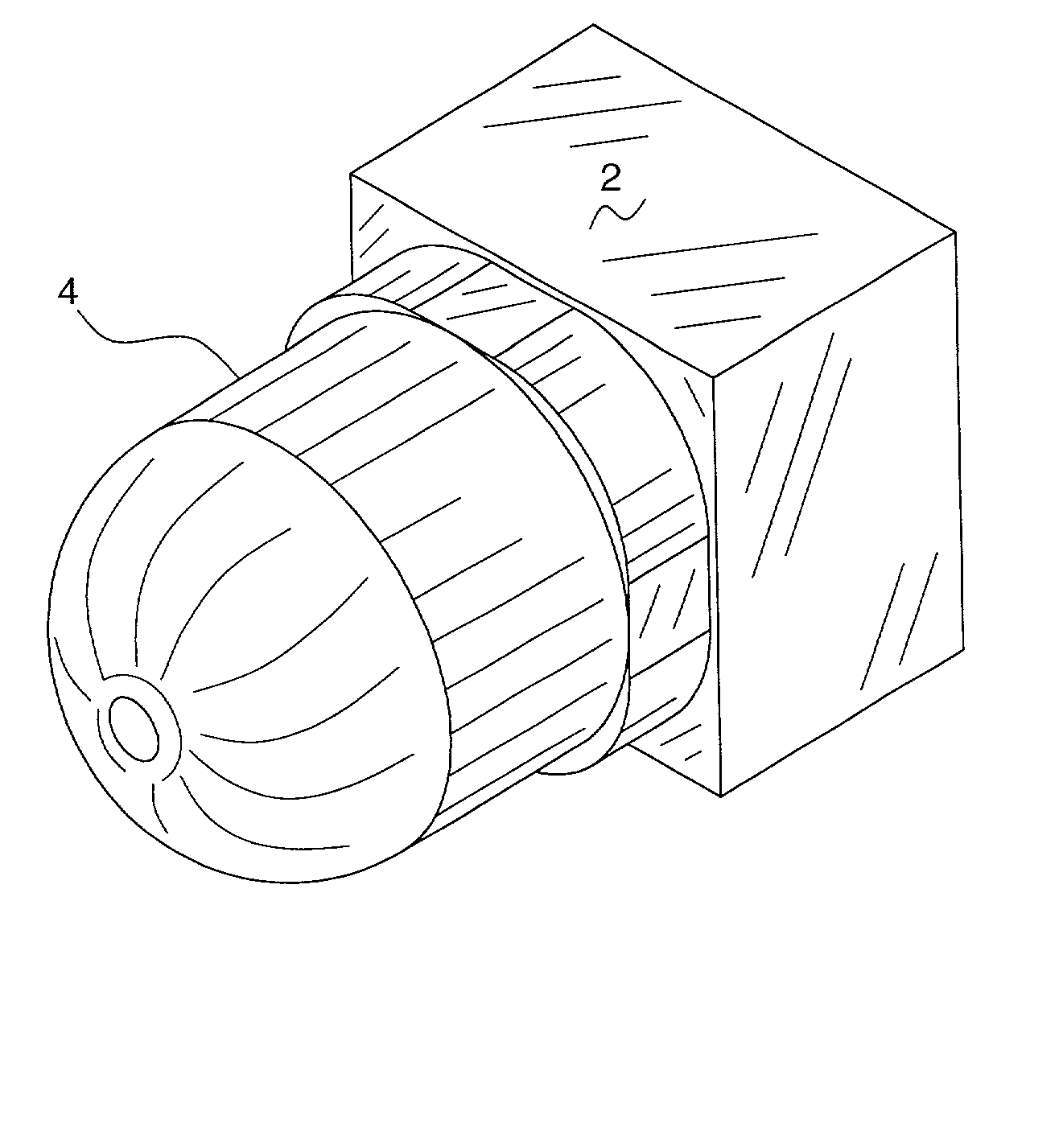
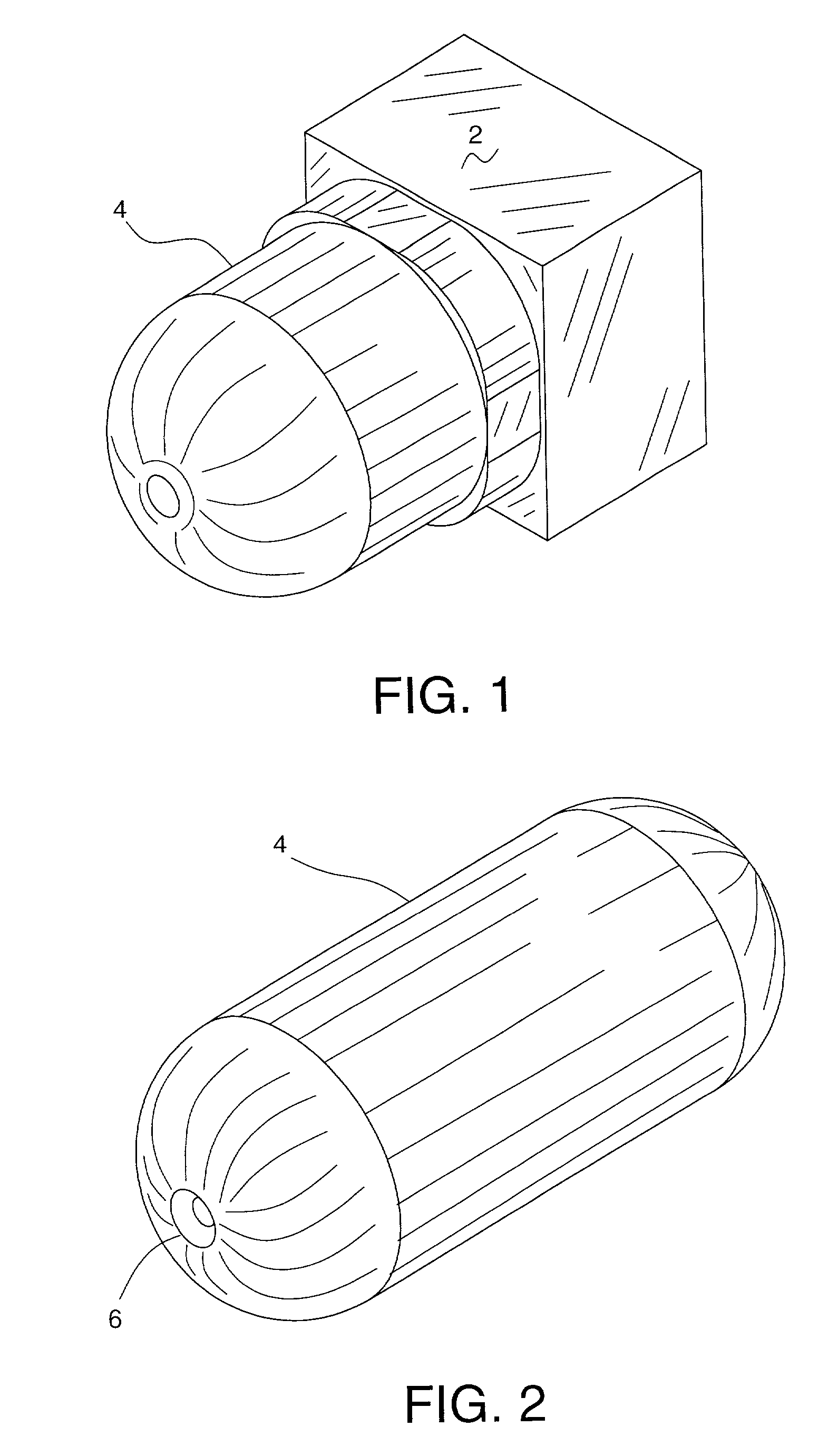
[0013] FIG. 1 is an isometric view showing the fabrication of a mandrel.

[0014] FIG. 2 is an isometric view showing the mandrel of FIG. 1 with a recess for one of the tank fittings.

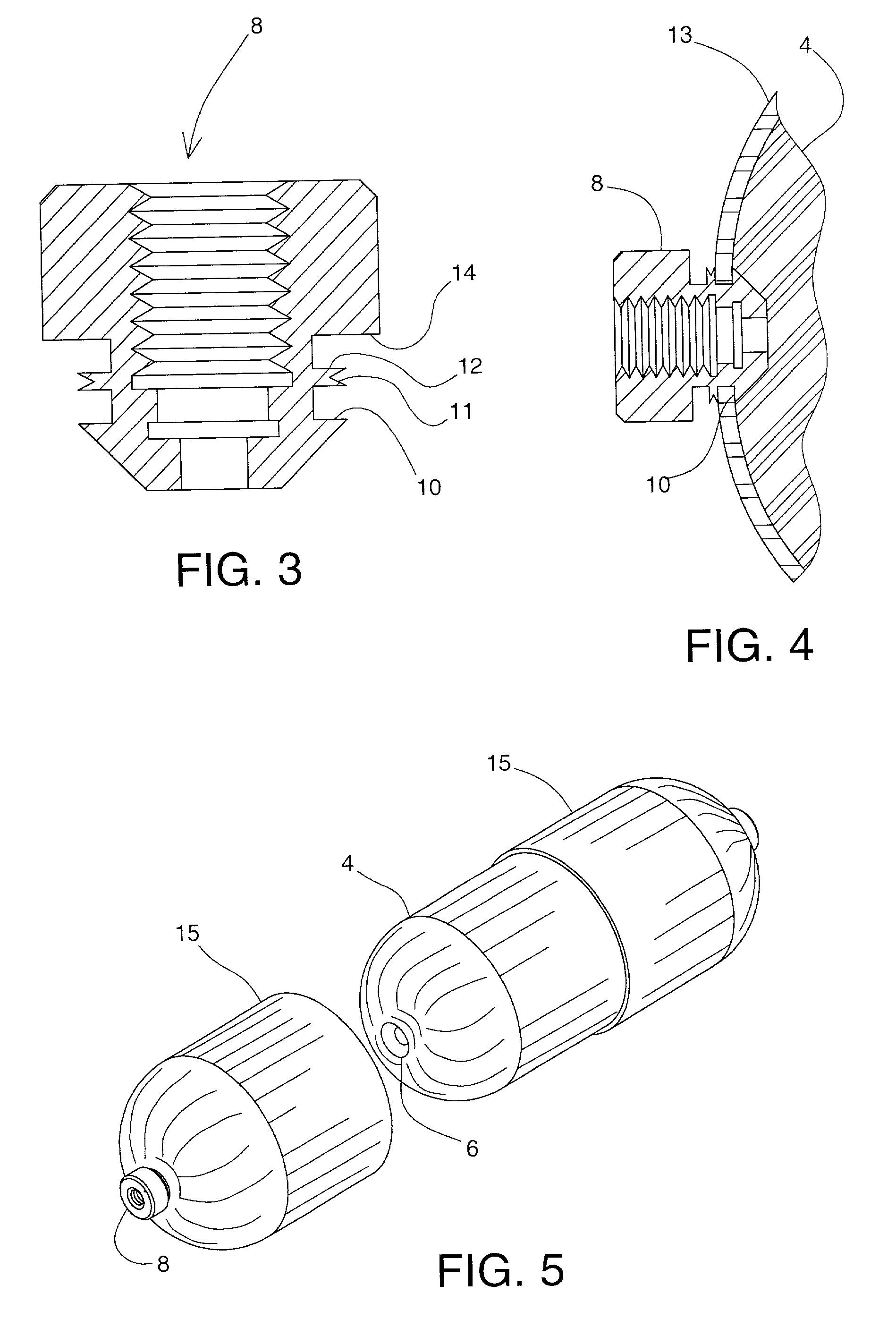
[0015] FIG. 3 is an enlarged cross sectional view of a tank fitting.

[0016] FIG. 4 is a cross sectional view showing a portion of the mandrel with a composite layer covering it and part of a tank fitting as an inner composite layer.

[0017] FIG. 5 is an isometric view showing the opening of the inner composite layer in order to remove the mandrel.

[0018] FIG. 6 is an isometric view showing the repaired inner composite layer following the removal of the mandrel.

[0019] FIG. 7 is a cross sectional view showing a portion the inner composite layer with a barrier layer deposited the...


PUM

PropertyMeasurementUnit
diameteraaaaaaaaaa
permeabilitiesaaaaaaaaaa
structureaaaaaaaaaa

Abstract

Two problems face fabricators of pressure tanks for space flight use. First, helium is the most common pressurant gas for launch vehicles, yet composite tanks, and liners used in other tanks carrying helium perform poorly. Pressure tanks fabricated using steel, aluminum, and copper are too heavy for space flight use. Second, cost is a considerable factor when tanks must be configured to fit in spaces of various sizes and shapes available for them. By the method herein pressure tanks having very low permeabilities for gases can be fabricated in various sizes and shapes. A mandrel is cut out of foamed plastic. It is then wrapped or overlayed with composite materials in three stages to form the pressure tank.

Description

CROSS-REFERENCE TO A RELATED APPLICATION[0001] My application entitled Method of Making a Composite Tank has now issued as U.S. Pat. No. 6,193,917. The patent discloses a method for making a composite tank for liquid oxygen, and the use of a water-soluble mandrel. A provisional application 60 / 285,913 was filed on Apr. 24, 2001.[0003] 1. Field of the Invention[0004] This invention, in one of its embodiments, provides a method for inexpensively producing composite pressure tanks having very low permeabilities for gases, for instance, tanks for upper stage spacecraft, and containers or other vessels for liquid helium and the like. Helium is the most common pressurant gas for launch vehicles. Non-metallic materials and liners used in tanks carrying helium perform poorly, indicating a need for tanks which confine gases such as helium with very little leakage. In another of its embodiments the invention affords a means for producing composite pressure vessels in many sizes and shapes with...

Claims


Application Information

Patent Timeline
Patent Type & Authority Applications(United States)
IPC IPC(8): B32B5/18B32B25/14B65D8/06B65D8/08
CPCB32B5/18Y10T428/1369Y10T428/13B32B25/14B32B15/14B32B15/20B32B1/02B32B2311/12B32B2311/22B32B5/245B32B25/10B32B2266/0278B32B2266/0264
Inventor DELAY, THOMAS K.
Owner NASA
Why Eureka
Try Eureka