Eureka AIR delivers breakthrough ideas for toughest innovation challenges, trusted by R&D personnel around the world.

Method and system for route table minimization

Inactive Publication Date: 2002-11-07
LEVEL 3 COMM LLC +2
View PDF11 Cites 30 Cited by
  • Summary
  • Abstract
  • Description
  • Claims
  • Application Information

AI Technical Summary

Benefits of technology

0014] The described embodiments avoid the situation where all preferred path information must be stored by all routers. On

Problems solved by technology

Because routing tables contain routes for a large number of destinations, the tables can become quite voluminous.
As a network (such as the Internet) grows, the size of the routing tables becomes problematic.
This problem is greater at customer locations using inexpensive routing equipment with a small amount of routing table storage.

Method used


Image

  • Method and system for route table minimization
  • Method and system for route table minimization
  • Method and system for route table minimization

Examples


Embodiment Construction

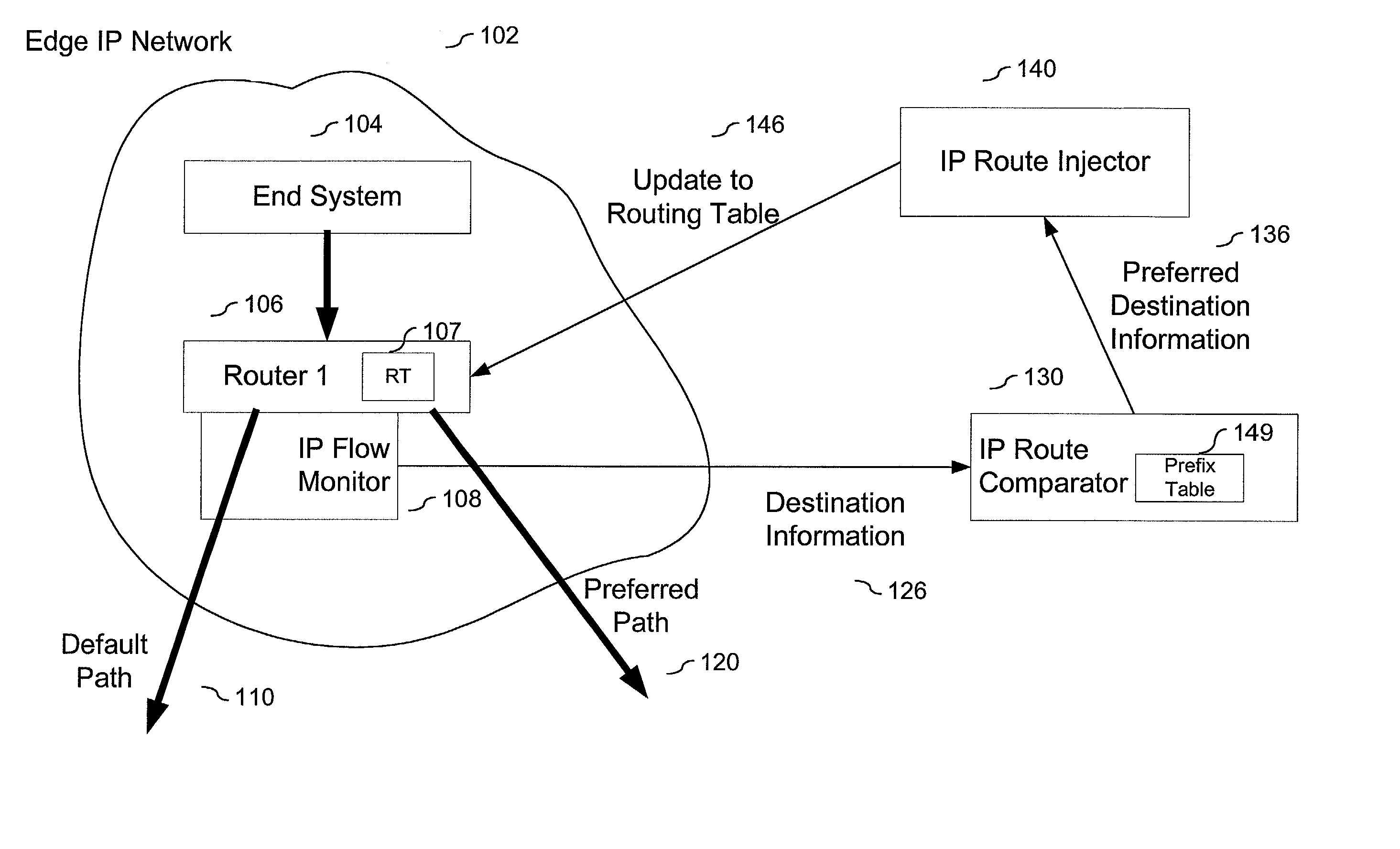
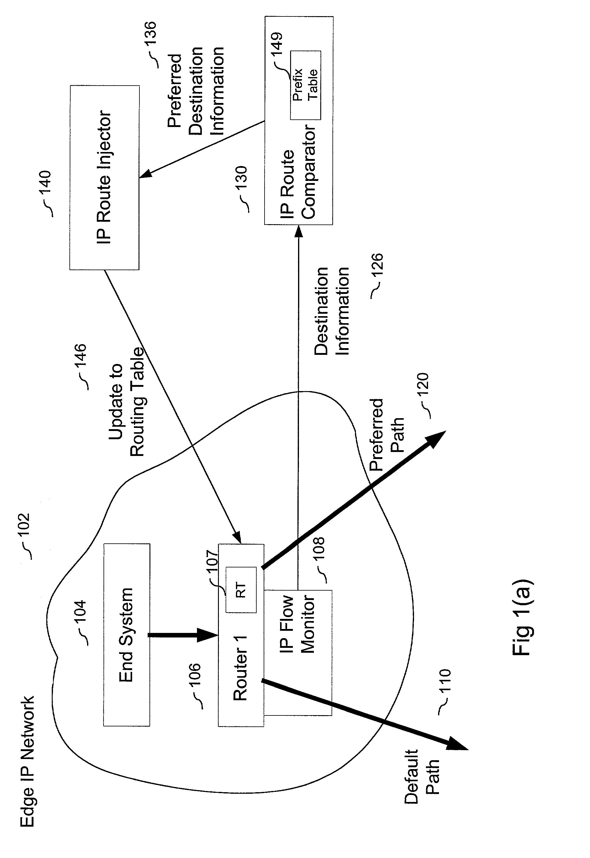
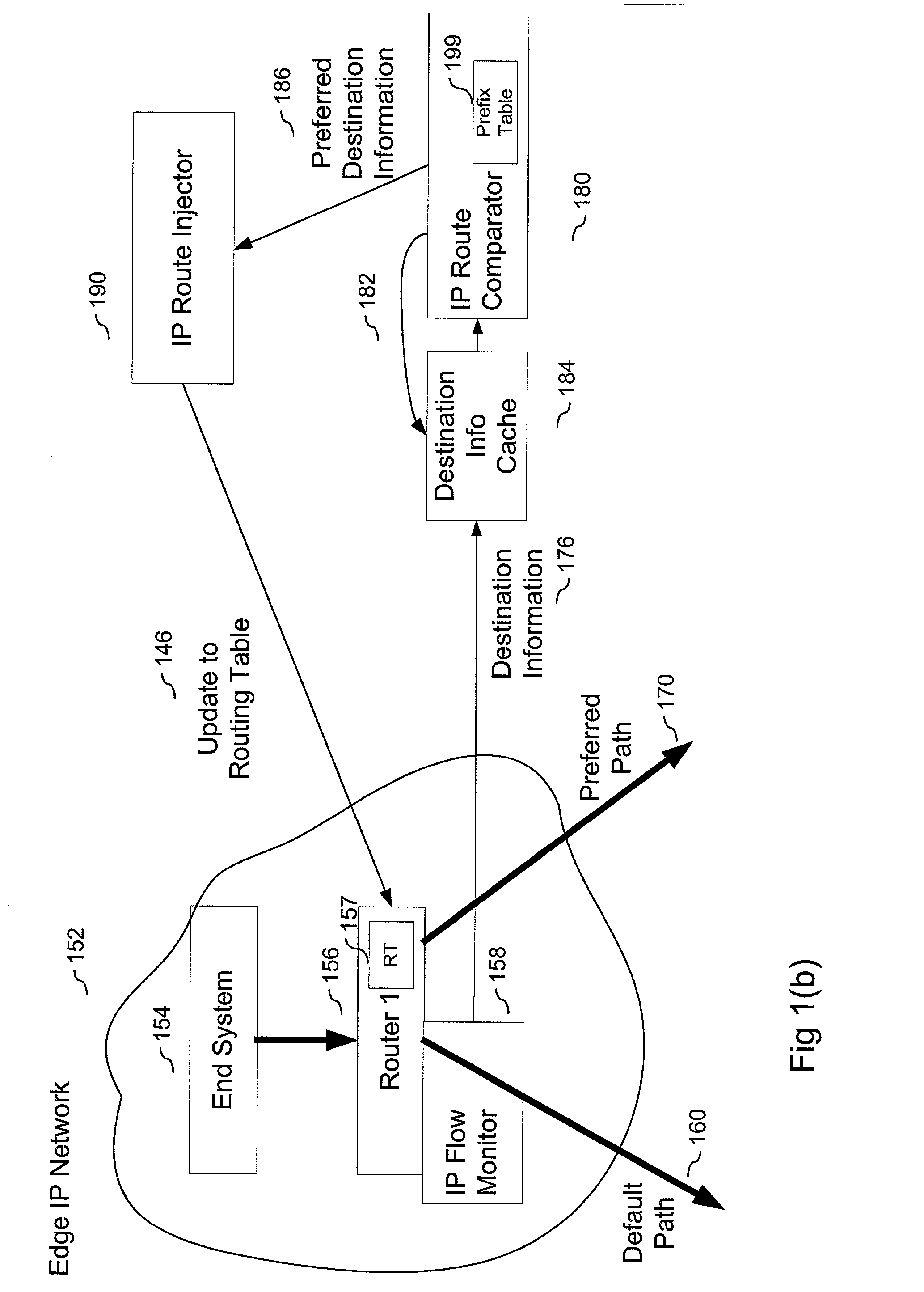
[0011] The described embodiments of the present invention use an IP flow monitor in conjunction with an IP route comparator and an IP route injector to create minimum size routing table stored in router of an IP network.

[0012] The IP flow monitor monitors information, such as destination information that identifies and differentiates one IP flow from another. The monitored information is passed to the IP route comparator, which determines if the monitored flow should use the preferred path. If so, the preferred path information is passed to the IP route injector, which in turn passes it to the router in the edge sub-network. The router updates its routing table in accordance with the new routing information.

[0013] In the described embodiment, the IP flow monitor is coupled to at least one preferred path between the sub-network and another sub-network. If a first packet in an IP dataflow is sent over the default connection, it is monitored, which indirectly causes the routing table t...


PUM


Abstract

A method and system that includes an IP flow monitor in conjunction with an IP route comparator and an IP route injector to minimize the size of routing tables that need to be stored in a router of an IP network. The IP flow monitor monitors information, such as destination information that identifies and differentiates one IP flow from another. The monitored information is passed to the IP route comparator, which determines if it has stored preferred path information for the IP flow identified by the monitored information. If so, the preferred path information is passed to the IP route injector, which in turn passes it to the router in the edge network. The router updates it routing table in accordance with the new routing information. Other described embodiments include an embodiment having a cache and embodiments in which one or both of the IP route comparator and the IP route injector are local to the network (instead of being local). Still another embodiment includes a local IP route comparator that accesses preferred path information stored on a remote database.

Description

[0001] A. Technical Field[0002] This application relates to a method of transferring data over one or more networks and, more specifically, to a method of minimizing the storage associated with routing tables in network devices connecting one or more networks.[0003] B. Background of the Invention[0004] The growth of the Internet, and the World Wide Web (Web) in particular, has led to enormous increases in the amount of traffic flowing over the group of connected networks that comprise the Internet and connected network systems. Access providers such as Internet Service Providers (ISPs) provide connections for businesses and individuals to connect to the Internet and access the Web. ISPs and other networks, such as intranets and extranets, must interconnect in order to allow their customers to reach points on the Internet serviced by other ISPs and / or other networks.[0005] The Internet is currently implemented using the TCP and IP protocols, which allow information to be routed withi...

Claims


Application Information

Patent Timeline
IPC IPC(8): H04L12/56
CPCH04L12/5602
Inventor BROWN, MICHAEL
Owner LEVEL 3 COMM LLC
Why Eureka
Eureka Blog
Learn More