Eureka AIR delivers breakthrough ideas for toughest innovation challenges, trusted by R&D personnel around the world.

Overload protector structure of extension cord receptacle

Inactive Publication Date: 2002-11-28
ATOM TECHNOLOGIES
View PDF0 Cites 1 Cited by
  • Summary
  • Abstract
  • Description
  • Claims
  • Application Information

AI Technical Summary

Problems solved by technology

However, too many plugs plugged together in one extension cord receptacle might inevitably increase the load of the extension cord receptacle and tend to over load the current.
1. Since too many soldering joints are produced for disposing the overload protector (93), as shown in FIG. 12, four soldering joints (99A, 99B, 99C, 99D) are required between the power line (94) as well as the overload protector (93) of the extension cord receptacle (9) and the switch (92). So many soldering points (99A, 99B, 99C, 99D) not only increase the difficulty and time in assembling, but also make the QC (Quality Control) workers spend more time in inspecting all the soldering joints (99A, 99B, 99C, 99D) one by one. And so many soldering joints (99A, 99B, 99C, 99D) might increase the probability of defects of the product due to the imperfect soldering joints (99A, 99B, 99C, 99D) and that is unfavorable for enhancing the good yield ratio of the product.
2. The overload protector (93) is presented as a separate unit linked with the switch (92) via the conducting line (95). Therefore the overload protector (93) occupies a certain space in the extension cord receptacle (9) and that is unfavorable for designing a light, thin, short and small extension cord receptacle (9).
3. The overload protector (93) is an independent component difficult to be further simplified with fixed components as well as assembly cost and is not a starting point for saving the manufacturing cost.
4. The overload protector (93) and the switch (92) are soldered to connect via the conducting line (95) and they might split to separate from each other.

Method used


Image

  • Overload protector structure of extension cord receptacle
  • Overload protector structure of extension cord receptacle
  • Overload protector structure of extension cord receptacle

Examples


Embodiment Construction

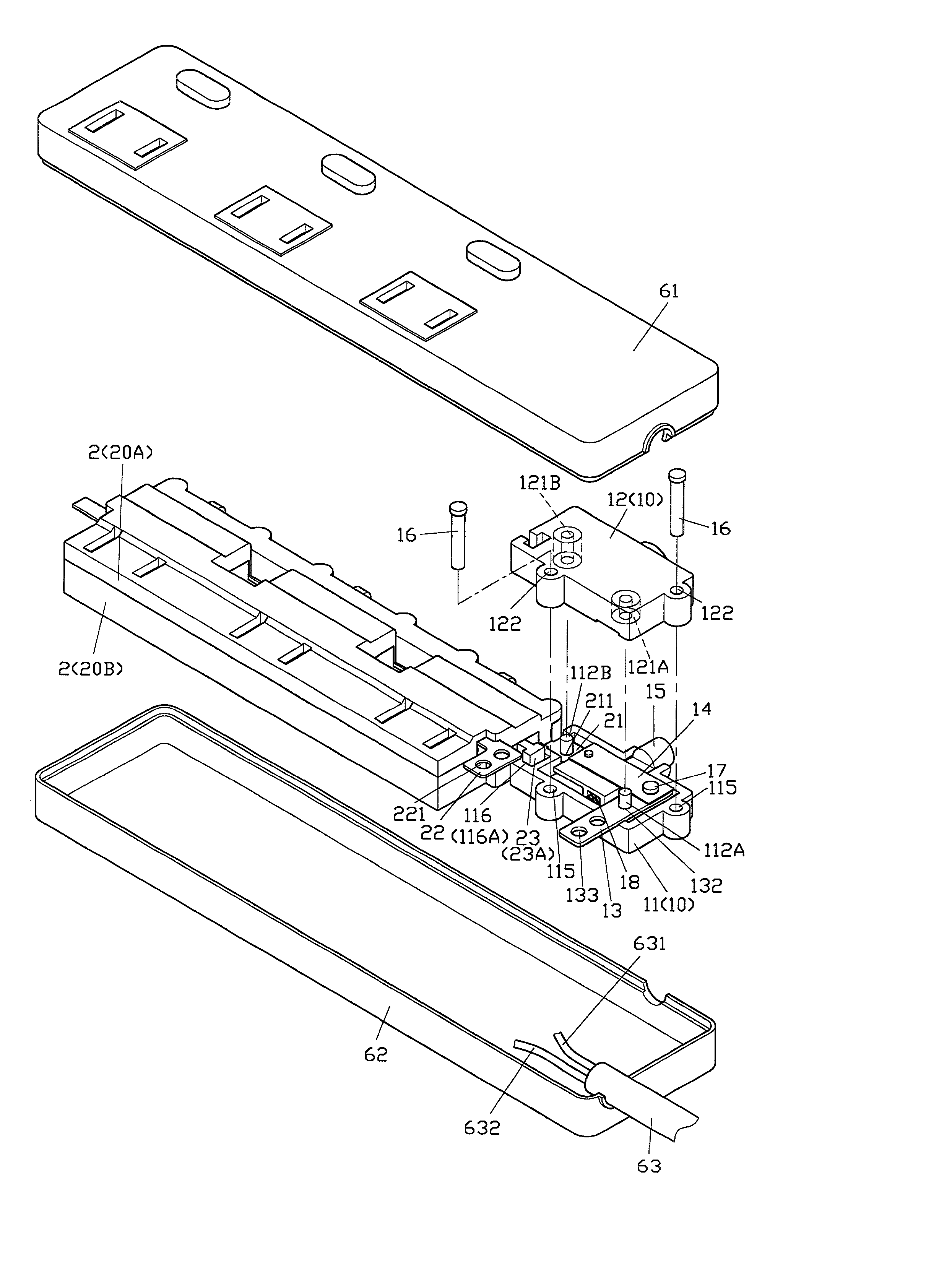
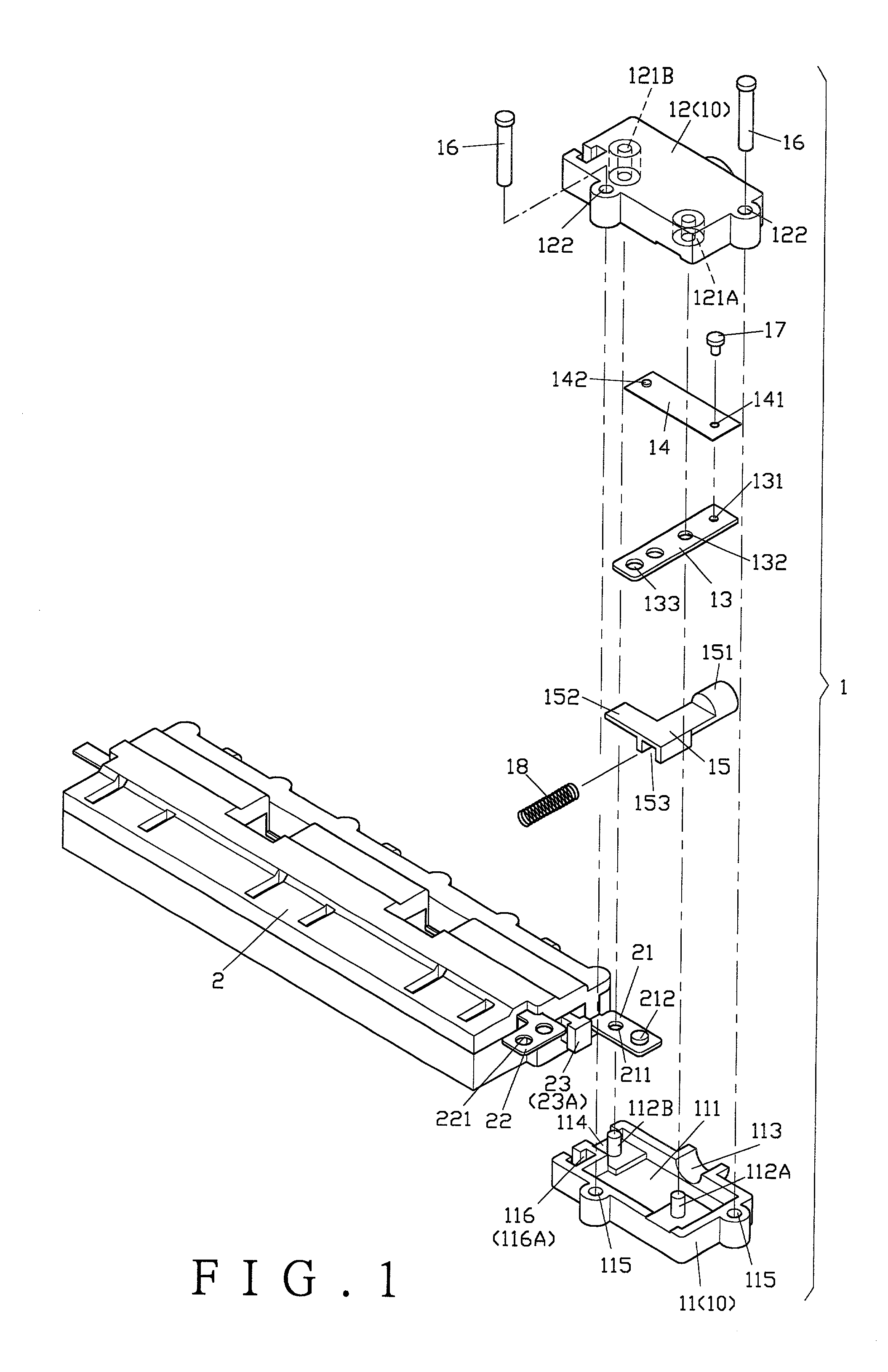
[0023] FIG. 1 shows one of the embodiments of the present invention, an overload protector (1) comprises of a housing member (10), a power input plate (13), a temperature sensing plate (14) and a press-button (15) with work elastic force.

[0024] The housing member (10) comprises a lower housing seat (11) and an upper housing seat (12). The lower housing seat (11) has a concave space (111) for accommodating a power input plate (13), a temperature sensing plate (14) and a press-button (15) thereafter. The lower housing seat (11) further has two convex columns (112A, 112B) disposed therein, a channel (113) for a press section (151) of a press-button (15) to be installed thereafter to extend outside the lower housing seat (11), and a slot channel (114) for a fire wire conducting plate (21) of an external component to be inserted for assembling. A plurality of conjoining holes (115) are disposed on the wall area of the lower housing seat (11). In addition, the lower housing seat (11) furt...


PUM


Abstract

The present invention relates to an overload protector structure of an extension cord receptacle that mainly comprised a fire wire conducting plate of a switching unit (or a receptacle unit) connected with an overload protector in the extension cord receptacle to extend properly; the overload protector has a housing member, a power input plate exposed at the said housing member, a temperature sensing plate is fixedly connected to an inner end of the power input plate, the said overload protector further penetrates outward through a slot channel from a contact point, the fire wire conducting plate can fitly extend into the said slot channel and contacts with the contact point of the temperature sensing plate; thereby, the effectiveness of rapid connection and eliminating the soldering joint point is possessed between the overload protector and the switch unit (or the receptacle unit).

Description

[0001] 1) Field of the Invention[0002] The present invention relates to an overload protector structure of an extension cord receptacle, more especially an overload protector structure that simplifies the joint point structure of an overload protector and provides a simple connecting method to enable the overload protector to be rapidly assembled in the extension cord receptacle and to reduce the number of the soldering joint points.[0003] 2) Description of the Prior Art[0004] Accordingly, seat bodies of available extension cord receptacles usually provide multiple receptacles for plugging the plugs (some extension cord receptacles have additional switches for controlling the on / off of the power). That not only effectively extends the supply of the power, but also divides the original single receptacle into multiple receptacles so that the power can be supplied to more electrical products. However, too many plugs plugged together in one extension cord receptacle might inevitably inc...

Claims


Application Information

Patent Timeline
IPC IPC(8): H01R13/713H01R25/00
CPCH01R25/003H01R13/7137
Inventor HUANG, CHYONG-YEN
Owner ATOM TECHNOLOGIES
Why Eureka
Eureka Blog
Learn More