Method of soldering or welding components

a technology of soldering or welding components, applied in the direction of soldering devices, manufacturing tools, auxillary welding devices, etc., can solve the problems of limited time available, suffer the quality of the soldering or welding seam to be produced, etc., to achieve the effect of reducing quality, increasing progressing speed, and increasing production speed for fixing seams

Active Publication Date: 2014-04-01
FFT PRODIONSSYST
View PDF39 Cites 69 Cited by
  • Summary
  • Abstract
  • Description
  • Claims
  • Application Information

AI Technical Summary

Benefits of technology

[0009]The fixing seam merely has to fix the components relative to each other in a joining position and can therefore be relieved of any other functions. In particular, it does not have to already fulfil the demands with regard to porosity. Correspondingly, the fixing seam can be produced at a greater progressing speed than conventional soldering or welding seams which are produced as a finished seam in only one process step. In order to fulfil its geometry-forming function, the fixing seam could in principle be embodied as a stitching and / or quilting seam, i.e. as a discontinuous seam with interruptions, but is preferably produced as a continuous seam. Since no particular demands have to be made on the quality of the material structure of the fixing seam, in particular the absence or at least low level of pores, the fixing seam can advantageously be produced continuously in the longitudinal direction of the joint. If the fixing seam is produced as a quilting seam, the interruptions in the seam are however only so long that the geometry-forming function is fulfilled despite the interruptions, and it is ensured that the components cannot be ajar from each other along the joint when they are only held to each other by means of the fixing seam, as viewed via the joint. The fixing seam is, at least in this sense, continuous and not a stitching seam in the broadest sense. Producing a geometry-forming fixing seam also has the advantage that the components which in accordance with the invention have already been joined in a geometry-forming way, i.e. in a geometry-preserving way in the above sense, no longer have to be tensed in order to complete the seam, but rather the components can be released as soon as the fixing seam has been produced, such that in the subsequent second process step, the volume-forming layer can be deposited or the fixing seam can be re-melted without any obstruction from clamps of a tensing means. With regard to the time pressure, the fact is also advantageously brought to bear that producing the fixing seam is not a matter of introducing the entire volume of a finished seam into the joint while using additional material. In the preferred first method variant, more connecting material is in fact advantageously introduced when producing the volume-forming layer. If the production speed for the fixing seam can already be increased due to the reduced quality demands, then the production speed can be further increased by reducing the connecting material to be introduced per unit of length.
[0010]The volume-forming layer or compacting re-melt is preferably produced at an advancing speed which is lower as compared to the fixing seam along the joint and can correspond to the advancing speed which is usual for conventional connecting seams. In the preferably two-tier finished seam, the volume-forming layer is the covering seam and can be produced with a very smooth outer surface and low porosity due to the production speed and / or advancing speed being lower as compared to the fixing seam. If soldering or welding material is introduced as an additional material in two steps, it is also possible to reduce the soldering or welding material to be introduced into the joint per process step, which enables the volume-forming layer—and, in principle, the fixing seam—to be produced at a higher production speed but to the same quality as conventional seams, or to be produced to a higher quality at the same production speed. In the case of the fixing seam, this gain in flexibility is preferably implemented as a higher production speed, while for the volume-forming layer, an increase in quality is preferred.

Problems solved by technology

In modern production lines, only a limited amount of time is available for the soldering or welding process, as a result of which the quality of the soldering or welding seam to be produced suffers.

Method used


Image

  • Method of soldering or welding components
  • Method of soldering or welding components
  • Method of soldering or welding components

Examples


Embodiment Construction

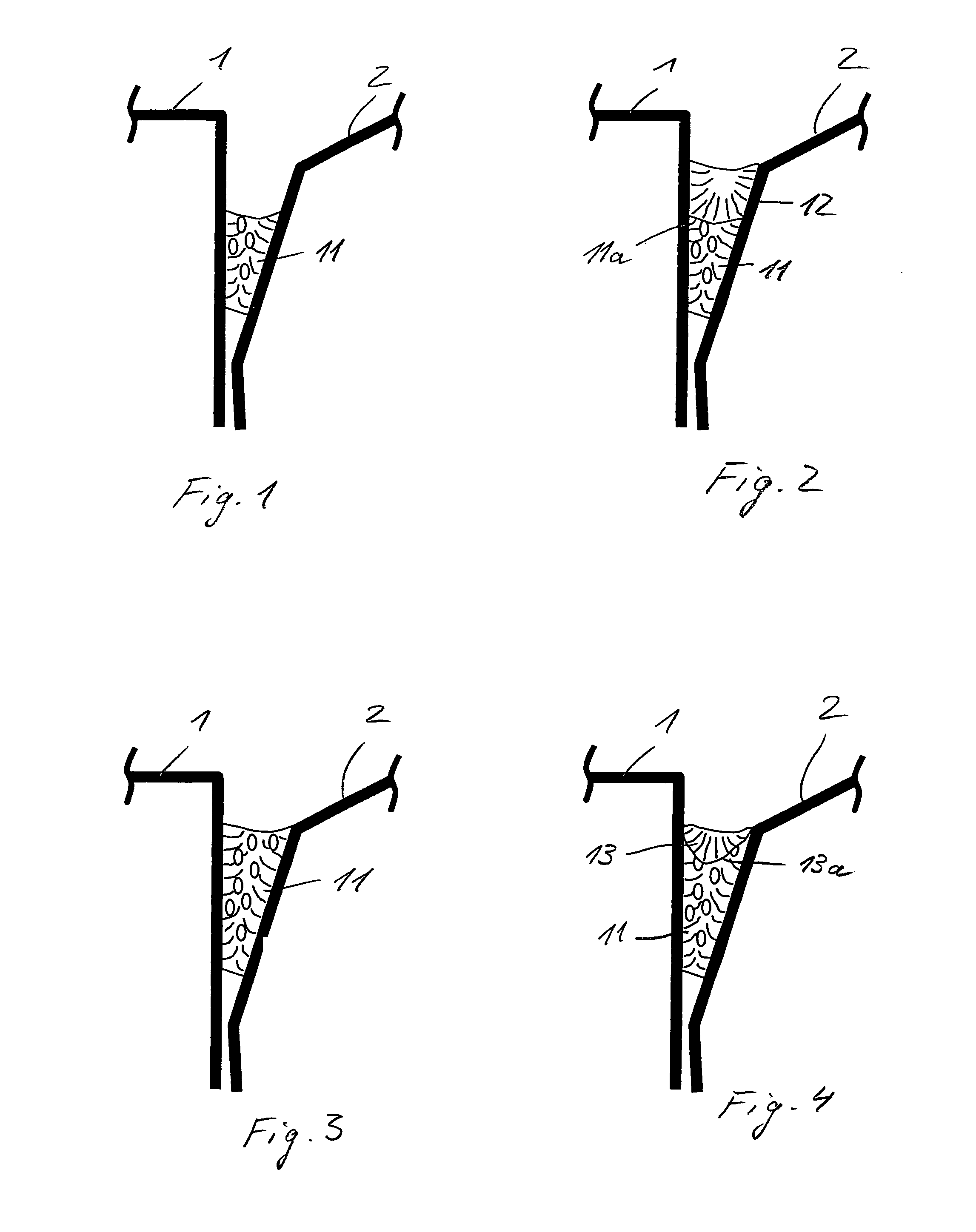
[0031]FIG. 1 show a cross-section of a component composite consisting of two components 1 and 2 and a fixing seam 11. The fixing seam 11 connects the components 1 and 2 along a jointly formed joint. Only the two flanks of the components 1 and 2 are shown, between which the joint and correspondingly the edges of the joint are formed. The component 1 is for example a side wall, and the component 2 is for example a metal sheet roof of a body shell of an automobile. The flank of the component 1 which faces the component 2 forms a progressive ratio relative to the component 2. The components 1 and 2 are in abutment at the base of the joint. The fixing seam 11 consists of a soldering material, for example a copper alloy or an aluminium alloy. The fixing seam 11 connects the components 1 and 2 permanently and fixedly to each other and in this sense has a geometry-forming effect on the component composite.

[0032]FIG. 2 shows the component composite after a covering layer 12 of soldering mate...


PUM

PropertyMeasurementUnit
diameteraaaaaaaaaa
diameteraaaaaaaaaa
diameteraaaaaaaaaa

Abstract

A method for soldering or welding components in a series production wherein: a fixing seam which connects the components (1, 2) is produced by melting a connecting material (3), which is supplied as an additional material or is formed by a base material of the components (1, 2), along a joint formed by the components (1, 2); and a volume-forming layer of connecting material is deposited onto the fixing seam by melting, or the fixing seam produced by means of the connecting material supplied as an additional material is re-melted.

Description

[0001]This application is the U.S. national phase application of PCT International Application No. PCT / EP2007 / 004159, filed May 10, 2007, which claims priority to German Patent Application to No. DE 10 2006 021 755.1, filed May 10, 2006.BACKGROUND OF THE INVENTION[0002]1. Technical Field[0003]The invention relates to: a method for soldering or welding components, preferably metal sheets, in a series production; a component composite produced by soldering or welding; a production line for joining components, including a production stage which includes soldering or welding; and lastly, a tool head which is particularly suitable for performing the method. The invention can in particular be used in the series production of vehicle body parts for soldering or welding metal body sheets. It is in particular suitable for joining metal sheets of the outer shell of vehicles, for example for joining a side part to a roof part, or for joining an outer metal sheet to an inner metal sheet of an a...

Claims


Application Information

Patent Timeline
Patent Type & Authority Patents(United States)
IPC IPC(8): B23K26/24B23K15/00
CPCB23K26/422B23K15/0006B23K15/0026B23K1/0056B23K1/005B23K2201/04B23K2201/006B23K2201/185B23K35/286B23K37/02B23K31/02B23K2201/34B23K35/302B23K26/24B23K15/10Y10T428/12736Y10T428/12493Y10T428/12951Y10T428/12903B23K26/702B23K2101/006B23K2101/04B23K2101/185B23K2101/34
Inventor SCHNEEGANS, JOCHENKRAFT, MARTIN
Owner FFT PRODIONSSYST
Why Eureka
Try Eureka