High illumosity lighting assembly

a lighting assembly and high illumination technology, applied in the direction of lighting and heating apparatus, semiconductor devices for light sources, coupling device connections, etc., can solve the problems of circuit boards, light source failure, and use of lighting assembly

Inactive Publication Date: 2007-02-27
ADVANCED THERMAL DEVICES
View PDF6 Cites 76 Cited by
  • Summary
  • Abstract
  • Description
  • Claims
  • Application Information

AI Technical Summary

Benefits of technology

[0008]The primary objective of the present invention is to provide an improved lighting assembly having a soldering plate removably provided thereto so as to provide secured engagement of the light emitting diodes (LEDs) on the base, a fixing plate securely connected to the base, a transparent plate mounted on top of the fixing plate and a cover securely connected to the fixing plate so as to sandwich therebetween the transparent plate to accomplish the goal of securing the LEDs on the base, and waterproofing with the introduction of a sealing material on the base as well as on the fixing plate.

Problems solved by technology

In order to best use the LEDs, a heat dissipation structure has to be provided or the lighting assembly using the LEDs as the light source will soon fail due to high temperature concentration.
However, during the processing of positioning the LED (70) on top of the circuit board (63), because there is no auxiliary tool or agent to help affix the LED (70) to the circuit board (63) and an adhesive gel has to be used, but after a long period engagement between the LED (70) and the circuit board (63) will become loose due to expansion / contraction from heat variation.

Method used


Image

  • High illumosity lighting assembly
  • High illumosity lighting assembly
  • High illumosity lighting assembly

Examples


Embodiment Construction

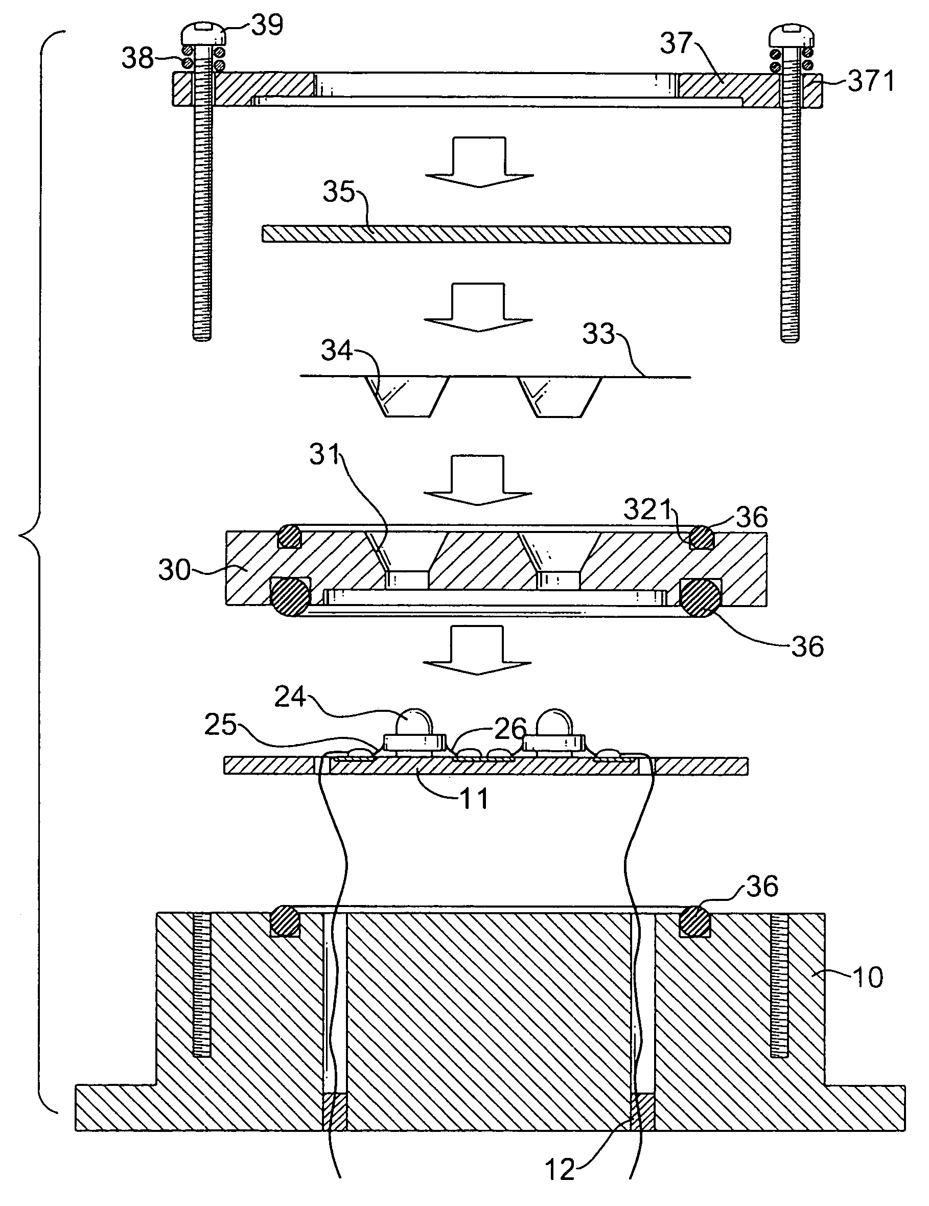
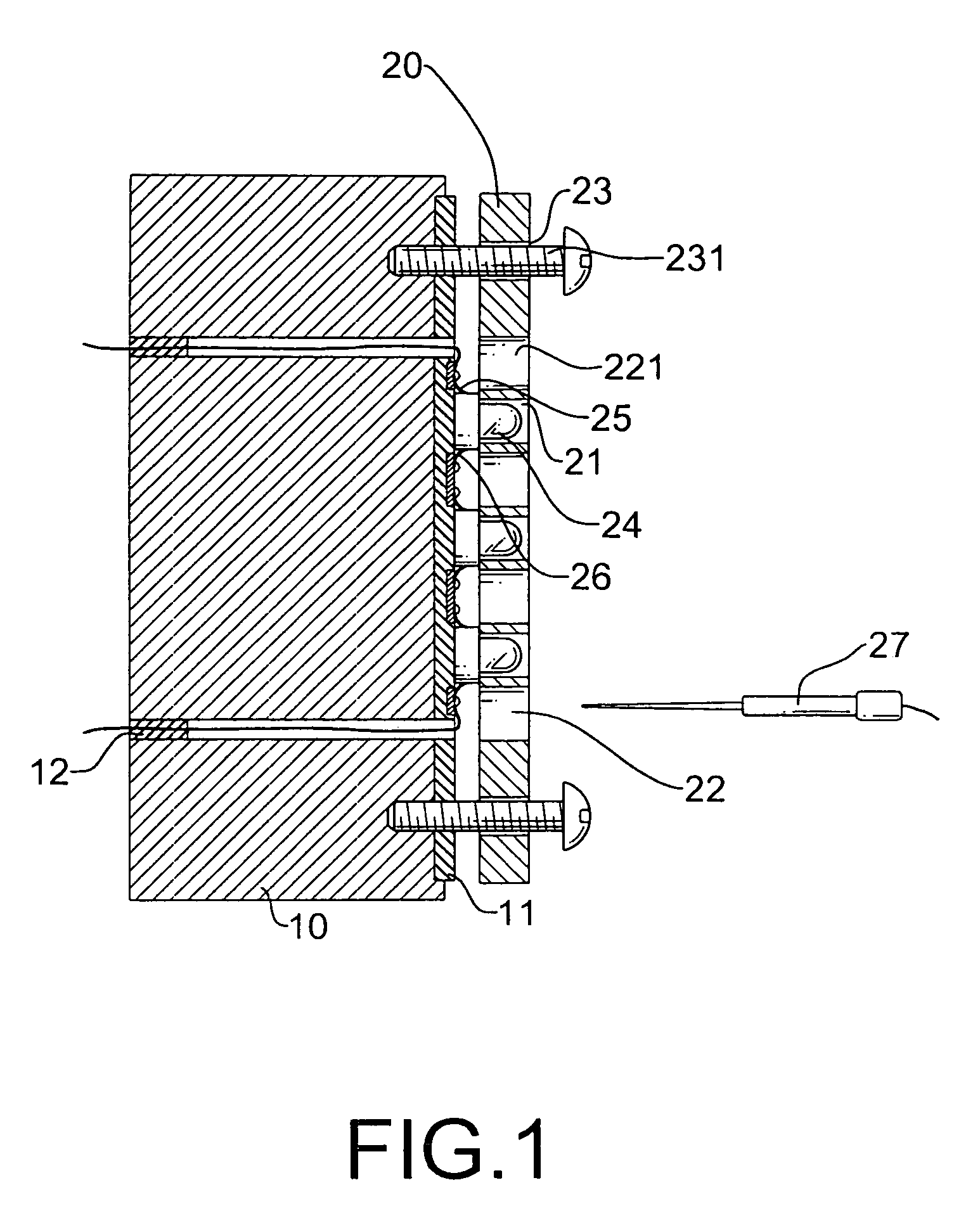
[0022]With reference to FIGS. 1 and 2, it is noted that the lighting assembly in accordance with the present invention includes a heat conductive base (10) having a circuit board (11) securely attached to a side of the heat conductive base (10) and multiple light emitting diodes (LEDs) (24) connected to the circuit board (11) and a soldering plate (20) removably connected to the heat conductive base (10).

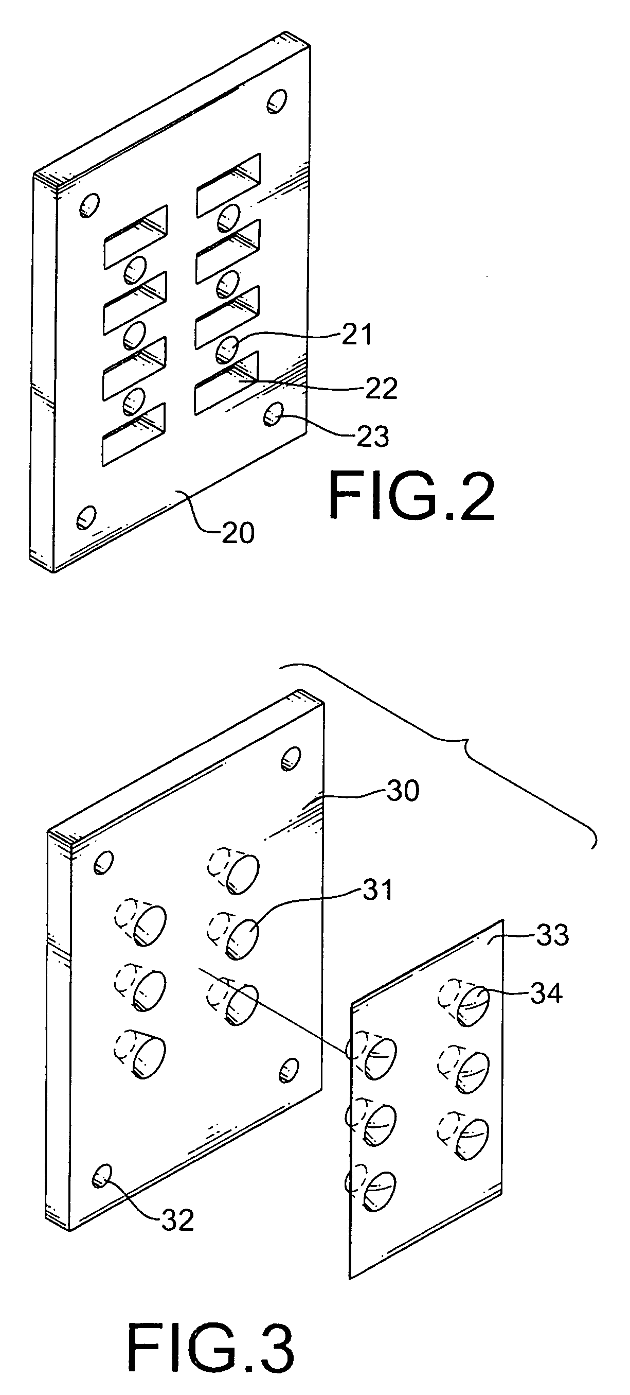
[0023]The soldering plate (20) is provided with multiple LED holes (21), multiple soldering holes (22) so arranged that a corresponding LED hole (21) sandwiched between two adjacent soldering holes (22) is aligned with a soldering nozzle (27), and screw holes (23) defined in corners of the soldering plate (20) to correspond to screws.

[0024]It is noted that when the soldering plate (20) is connected to the circuit board (11) and the heat conductive plate (10), screws (231) are extended through the screw holes (23) of the soldering plate (20), the circuit board (11) and the heat condu...


PUM


Abstract

A lighting assembly includes a circuit board having light emitting diodes, a heat conductive plate, a soldering plate removably connected to the circuit board and having multiple LED holes to correspond to the LEDs on the circuit board and a fixing plate securely connected to the circuit board after the soldering plate is removed from engagement with the circuit board. A cover has multiple positioning holes to allow extension of threaded bolts through the positioning holes, the fixing holes, the circuit board and into the heat conductive plate to secure engagement among the heat conductive plate, the circuit board, the fixing plate, the transparent plate and the cover.

Description

BACKGROUND OF THE INVENTION[0001]1. Field of the Invention[0002]The present invention relates to a high illuminosity lighting assembly, and more particularly to a lighting assembly having a soldering plate removably provided thereto so as to provide secured engagement of the light emitting diodes (LEDs) on the base, a fixing plate securely connected to the base, a transparent plate mounted on top of the fixing plate, and a cover securely connected to the fixing plate so as to sandwich therebetween the transparent plate to accomplish the goals of securing the LEDs on the base, and waterproof with the introduction of a sealing material on the base as well as on the fixing plate.[0003]2. Description of Related Art[0004]Light emitting diodes (LEDs) have been widely used in various fields. For example, conventional light bulbs in the traffic lights, warning lights or signaling lights are now changed to LEDs for better illuminosity and better lighting efficiency. In order to best use the ...

Claims


Application Information

Patent Timeline
Patent Type & Authority Patents(United States)
IPC IPC(8): H01R13/00
CPCF21K9/00F21V19/0035F21V29/004H01R33/09F21V29/74F21V31/005F21V29/2212F21Y2101/02F21V17/12F21V19/0055F21V23/002Y10S362/80F21Y2115/10F21V29/763
Inventor HUANG, BIN-JUINE
Owner ADVANCED THERMAL DEVICES
Why Eureka
Try Eureka