Easy mount connector

a technology of connectors and mounting nut nuts, which is applied in the direction of rod connections, coupling device connections, tractors, etc., can solve the problems of relatively labor-intensive process of threading the mounting nut onto the connector body of the connector component shown in fig. 3, and achieve the effect of quick and easy mounting the connector component, quick and easy completion, and quick and easy completion

Inactive Publication Date: 2002-12-12
INT TRUCK INTPROP LLC
View PDF0 Cites 24 Cited by
  • Summary
  • Abstract
  • Description
  • Claims
  • Application Information

AI Technical Summary

Benefits of technology

[0002] As a result,--an object of the present invention is to provide a connector component which is constructed in a manner allowing for relatively easy mounting of the connector component to a connector mounting component.
[0004] As mentioned above, the first retention structure and the second retention structure of the connector component have the purpose of maintaining proper engagement of the connector component to a connector mounting component. The first retention structure and the connector body are constructed in such a manner that the first retention structure may be engaged to the connector body adjacent a first end of the mounting portion of the connector body. The second retention structure and the connector body are constructed in such a manner that the second retention structure may be engaged to the connector body adjacent a second end of the mounting portion of the connector body. The construction of the first retention structure, the second retention structure, and the connector body are such that, when properly engaged to the connector body, the first retention structure and the second retention structure extend outwardly from the connector body in directions perpendicular to a central axis of the mounting portion of the connector body. Thus, when the connector component is properly mounted to a connector mounting component, movement of the connector body in directions parallel to the central axis of the mounting portion of the connector body eventually causes abutment between a portion of the connector mounting component adjacent the connector opening and either the first retention structure or the second retention structure. Thus, when the mounting portion of the connector body is disposed within the connector opening of a connector mounting component and the first retention structure and the second retention structure are properly engaged to the connector body, the mounting portion of the connector body is prevented from moving out of the connector opening.
[0006] Such a construction of a connector component allows an individual to rapidly and easily mount the connector component to or separate the connector component from a connector mounting component. With a quick connect clip of the first retention structure and / or the second retention structure of the connector component disengaged from a portion of the connector body adjacent a pilot portion, the pilot portion of the connector body may be inserted through the connector opening defined through a connector mounting component. After the pilot portion is inserted through the connector opening, the mounting portion may be slid into the connector opening defined by the connector mounting component to a point such that the first end of the mounting portion and the second end of the mounting portion are disposed upon opposite sides of the connector mounting component. Once the mounting portion of the connector body is so disposed within the connector opening, the connector body may be secured to the connector mounting component by engaging to the connector body any of the first retention structure and the second retention structure that were not previously engaged to the connector body. Engagement of any of the first retention structure and the second retention structure that are quick connect clips to the connector body may be quickly and easily accomplished by sliding or snapping the quick connect clip(s) into engagement with one or more retention structure slot(s) defined by the connector body. In order to subsequently separate the connector component of the present invention from the connector mounting component a quick connect clip of the first retention structure and / or the second retention structure that is engaged to the connector body adjacent a pilot portion may be disengaged from the connector body of the connector component. Disengagement of such a quick connect clip of the first retention structure or the second retention structure from the connector body may be quickly and easily accomplished by sliding or snapping the quick connect clip out of engagement with one or more retention structure slot(s) defined by the connector body. Once the first retention structure and / or the second retention structure are disengaged from a portion of the connector body adjacent a pilot portion, the mounting portion and the adjacent pilot portion of the connector body may be withdrawn from the connector opening defined by the connector mounting component. Thus, it can be seen that the above mentioned object of the present invention as well as others not mentioned have been met.

Problems solved by technology

Many such connector components are of a design that makes the process of securing the connector component to a connector mounting component relatively labor intensive.
The process of threading the mounting nut onto the connector body of the connector component shown in FIG. 3 is a relatively labor intensive process.

Method used


Image

  • Easy mount connector
  • Easy mount connector
  • Easy mount connector

Examples


Embodiment Construction

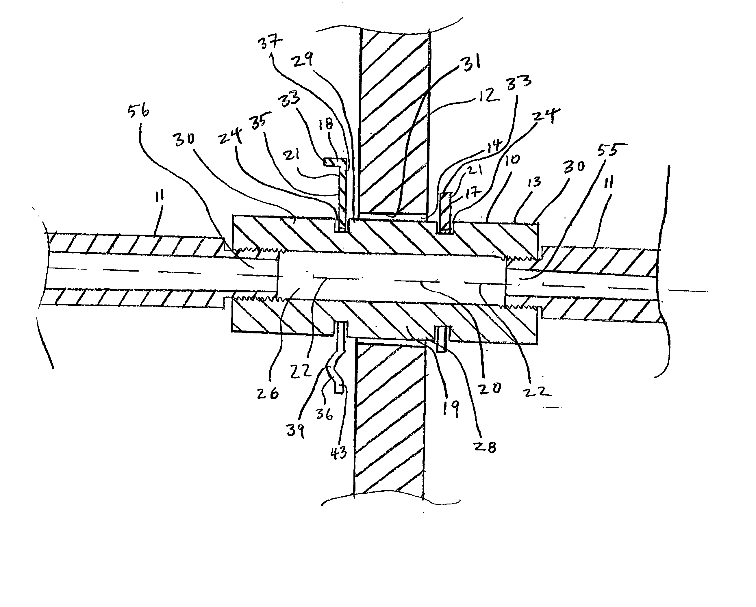
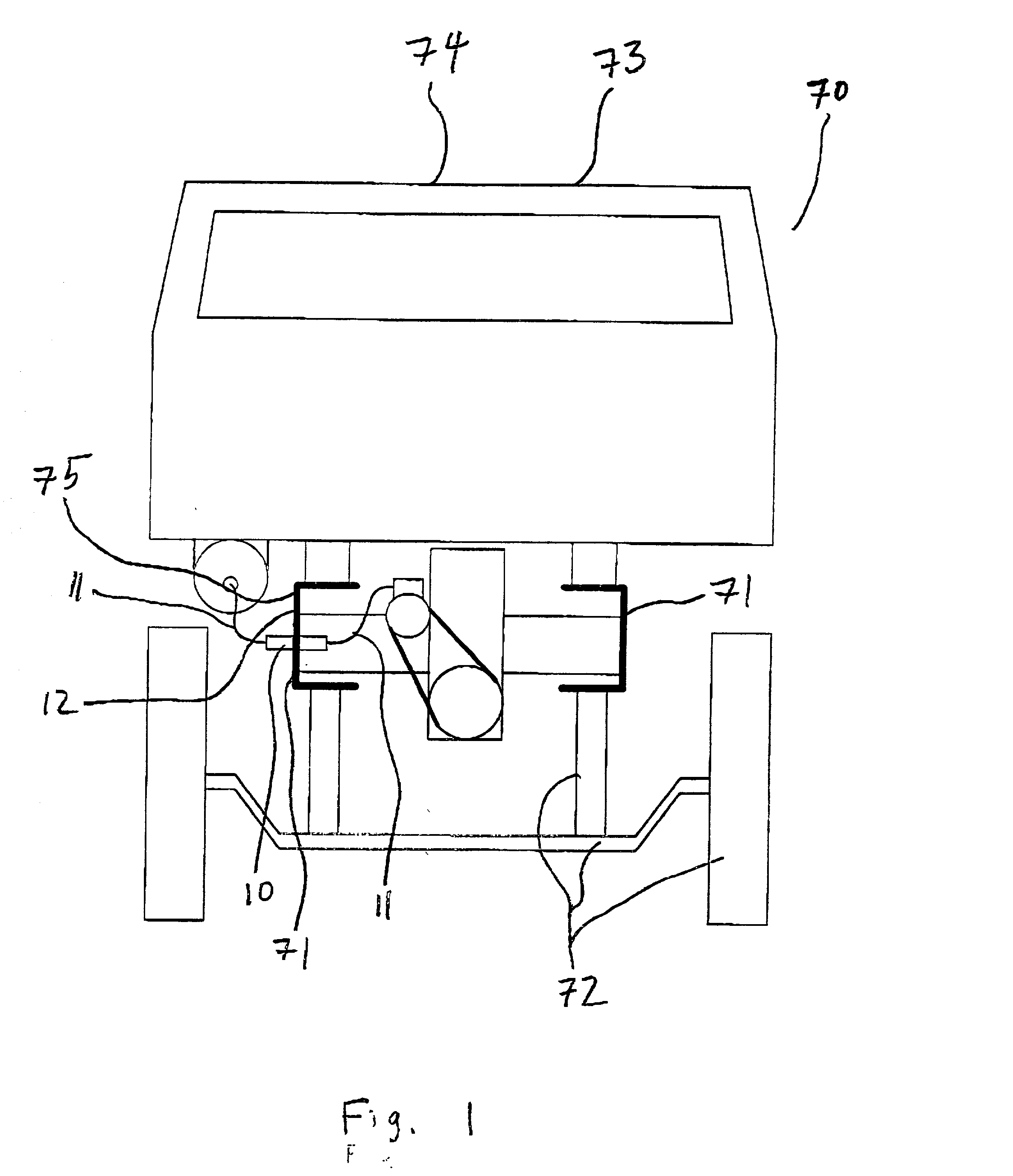
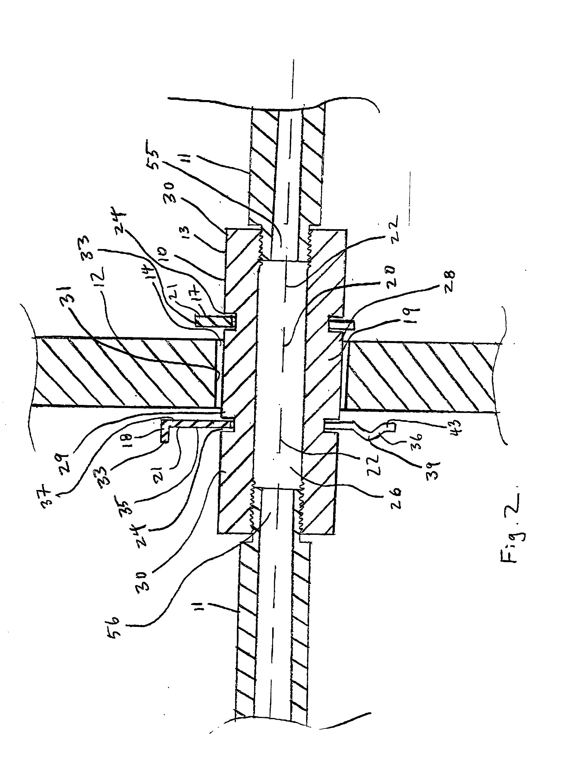
[0044] There is shown in the figures embodiments of a connector component 10 according to the present invention. The connector component 10 of the present invention is constructed to fluidly and / or electrically connect two or more device(s) 11 to one another. The connector component 10 of the present invention is also constructed to be mounted to and derive support from a connector mounting component 12. The connector component 10 of the present invention is also constructed in such a manner that it can be repeatedly mounted to and subsequently separated from the connector mounting component 12 in a relatively quick and easy manner.

[0045] The connector component 10 of the present invention may be constructed to fluidly connect two or more device(s) 11 to one another. The connector component 10 of the present invention comprises a connector body 13. The connector body 13 of a connector component 10 according to the present invention that is constructed to fluidly connect two or more ...


PUM


Abstract

A connector component for fluidly and / or electrically connecting two or more devices to one another is constructed in such a manner that it can be repeatedly quickly and easily mounted to and subsequently separated from a connector mounting component. The connector component includes a mounting portion that is disposed within a connector opening in the connector mounting component when the connector component is mounted to the connector mounting component. The connector component includes at least one quick connect clip such as an E-clip or snap ring clip that can be engaged to the connector component to maintain its attachment to the connector mounting component.

Description

[0001] This invention relates to connector components that fluidly and / or electrically connect two or more devices to one another and that are mounted to a connector mounting component. More specifically, the connector components that the present invention relates to are of a type that are generally mounted to a connector mounting component with a connector body of the connector component disposed within a connector opening defined through the connector mounting component. An example of a prior art connector component of this type is illustrated in FIG. 3. Many such connector components are of a design that makes the process of securing the connector component to a connector mounting component relatively labor intensive. The prior art connector component shown in FIG. 3 is an example of a connector component for which the process of securing the connector component to the connector mounting component is relatively labor intensive. The connector component shown in FIG. 3 has a mounti...

Claims


Application Information

Patent Timeline
Patent Type & Authority Applications(United States)
IPC IPC(8): F16B21/18F16L5/02F16L37/12H01R4/56H01R13/74H01R24/76H02G3/22
CPCF16B7/182F16B21/18F16L5/027H02G3/22H01R4/56H01R13/745F16L37/1225
Inventor MORYKON, PETER M.MANN, WILLIAM DENNIS
Owner INT TRUCK INTPROP LLC
Why Eureka
Try Eureka