Shaft drive coupling

Inactive Publication Date: 2002-12-19
F F SEELEY NOMINEES
View PDF8 Cites 6 Cited by
  • Summary
  • Abstract
  • Description
  • Claims
  • Application Information

AI Technical Summary

Problems solved by technology

Each cycle of temperature thereby results in an increase in load on the components, and an increase in stress in the parts of the components subjected to this load.
If this thermal and operational cycling is allowed to

Method used


Image

  • Shaft drive coupling
  • Shaft drive coupling
  • Shaft drive coupling

Examples


Embodiment Construction

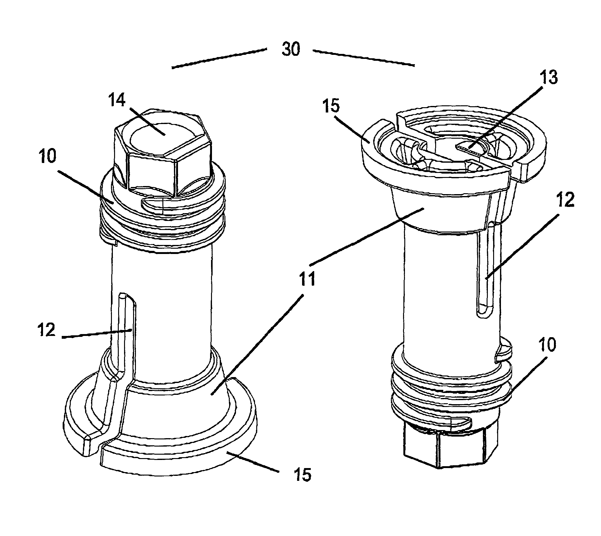
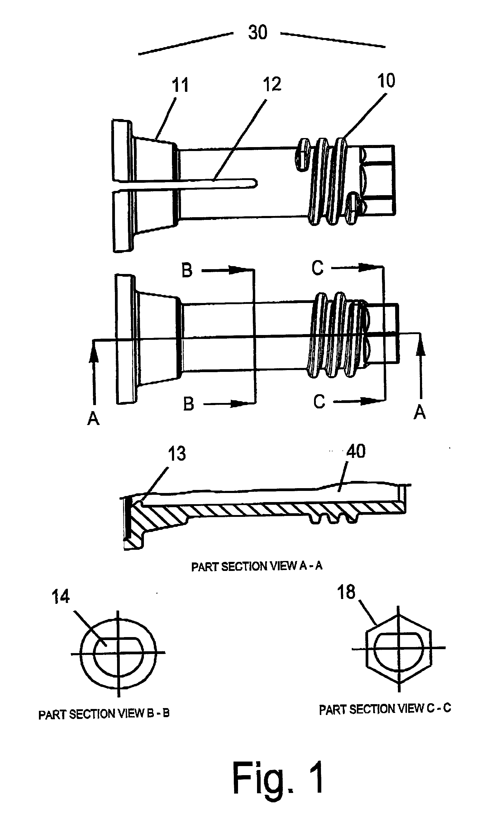
[0022] FIG. 1 shows a shaft drive coupling device 30 which is adapted to be fitted over a driving shaft 40 (partly shown in section A-A). The shaft drive coupling of this embodiment comprises a single component which has the features of a coarse, fast lead male thread 10, a tapered engagement 11, slotted relief 12, a "D" shaped bore 14 and an engagement projection 13. The male thread 10 may be left or right handed according to the direction of rotation of the driving and driven devices.

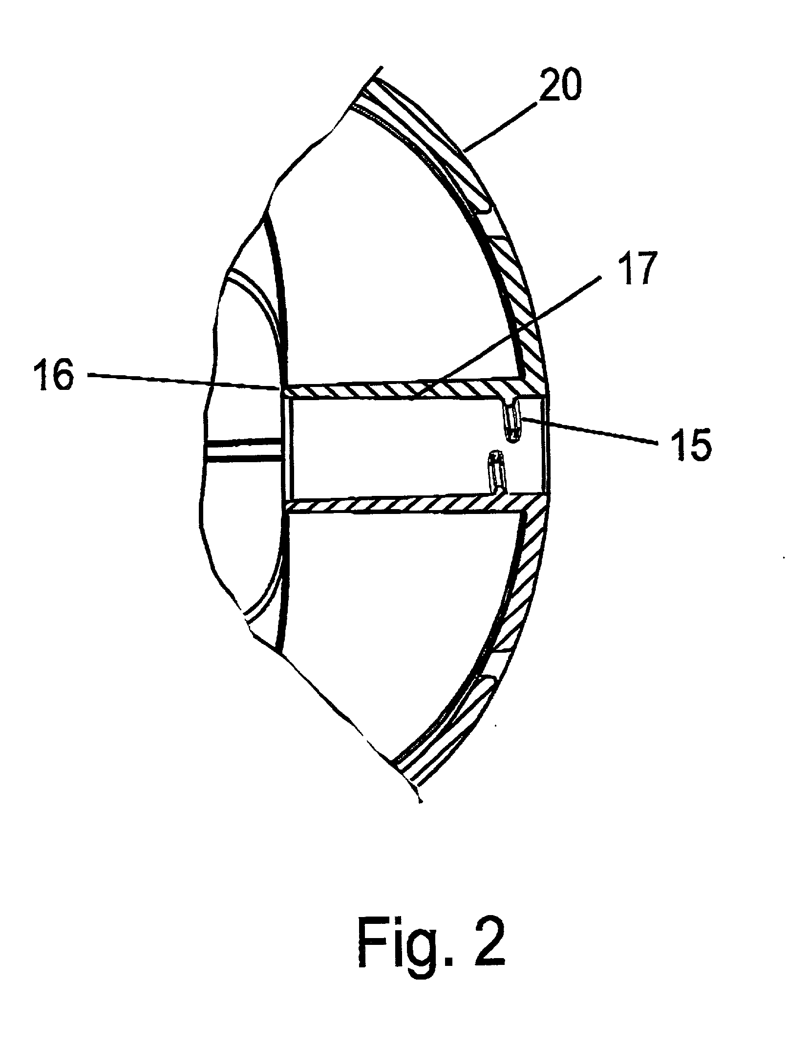
[0023] FIG. 2 shows a part section of driven device 20. The features on the driven device required for operation of the shaft drive coupling are a formed female thread 15 within the bore 17, and an engagement face 16.

[0024] FIG. 3 shows the shaft drive coupling 30 with the driven device 20 in the normal operating position. In this position, the female thread 15 of the driven device is engaged fully with the male thread 10 of the shaft drive coupling 30, while simultaneously the engagement face 16 of t...


PUM


Abstract

A single piece coupling device for connecting a load component to a rotatable shaft. The device comprises a sleeve having a bore for containing a rotatable shaft, an externally threaded portion and a tapered engagement face on the outer surface of the sleeve. Radial compression relief associated with the tapered engagement face is provided such that when the device is fitted on a shaft, and as the threaded portion engages with a corresponding threaded region on the load component, the tapered engagement face engages the load component and the compression relief enables the sleeve to be radially compressed to grip the shaft.

Description

[0001] This invention relates to a drive coupling for the connection of a load device to a rotating shaft while allowing for the ready disconnection of the load device.DESCRIPTION OF THE PRIOR ART[0002] Throughout this description and the claims which follow, unless the context requires otherwise, the word "comprise`, or variations such as "comprises" or "comprising", will be understood to imply the inclusion of a stated integer or step or group of integers or steps.[0003] The reference to any prior art in this specification is not, and should not be taken as, an acknowledgement or any form of suggestion that that prior art forms part of the common general knowledge in Australia.[0004] The requirement to connect a driven device to a shaft providing motive power is a situation arising in many appliances and industrial applications. The shaft providing motive power will generally be the output shaft of an electric motor, but may be another intermediate driven shaft as will be the case...

Claims


Application Information

Patent Timeline
IPC IPC(8): F16D1/091F16D1/096
CPCF16D1/096Y10T403/7052Y10T403/73Y10T403/7058F16B2200/67
Inventor HARRISON, JAMES ROBERTMILLER, DAVID WILLIAM
Owner F F SEELEY NOMINEES
Why Eureka
Try Eureka