Image correction method and image correcting apparatus
- Summary
- Abstract
- Description
- Claims
- Application Information
AI Technical Summary
Problems solved by technology
Method used
Image
Examples
Embodiment Construction
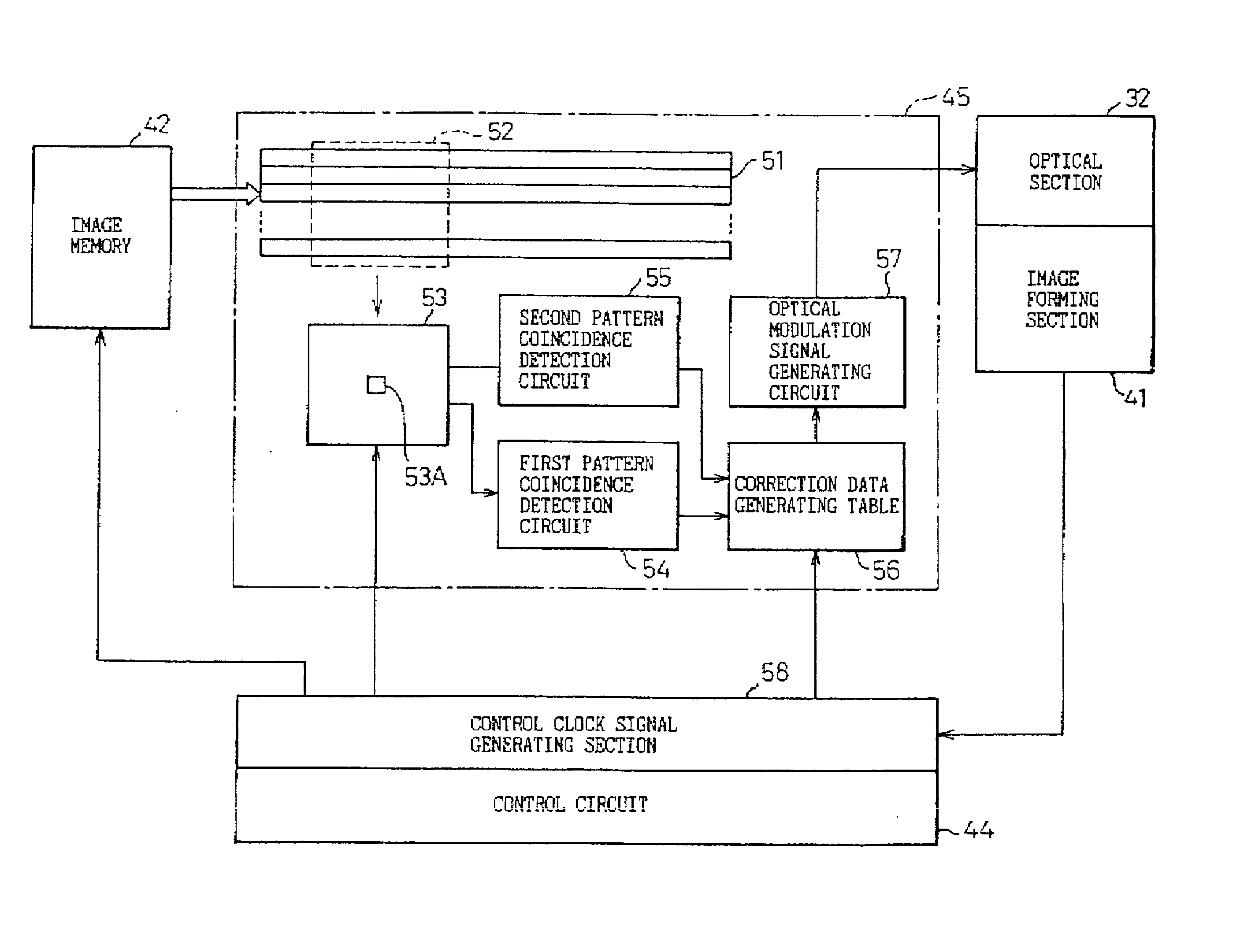
[0035] Now, the present invention will be described below with respect to an embodiment in which the invention is applied to image data printed by a laser beam printer so as to improve the quality of the printed image.
[0036] FIG. 6 is a view showing an example of the construction of a laser beam printer.
[0037] Reference number 31 denotes the main body of the laser beam printer. The main body 31 is comprised of an optical section 32 and an image forming section 41. The optical section 32 is comprised of a laser 33 that outputs laser beam, a polygon mirror 34 that deflects the laser beam so as to perform scanning with the beam repeatedly, a mirror motor 35 that drives and rotates the polygon mirror 34, and a beam detector 36 that detects start of scanning of the scanned laser beam. The image is forming section 41 is comprised of a photosensitive drum 37, a development station 38, a transfer roller 40, and a turn-around mirror 39. The surface of the photosensitive drum 37 is electrifie...
PUM
 Abstract
Description
Claims
Application Information
 - R&D
- Intellectual Property
- Life Sciences
- Materials
- Tech Scout
- Unparalleled Data Quality
- Higher Quality Content
- 60% Fewer Hallucinations
Browse by: Latest US Patents, China's latest patents, Technical Efficacy Thesaurus, Application Domain, Technology Topic, Popular Technical Reports.
© 2025 PatSnap. All rights reserved.Legal|Privacy policy|Modern Slavery Act Transparency Statement|Sitemap|About US| Contact US: help@patsnap.com


