Device for collecting liquid from exhalation gas from a patient

a technology for exhalation gas and patient, which is applied in the direction of suction devices, respirators, respiratory apparatus, etc., can solve the problems of affecting the patient's life, affecting the patient's health,

Inactive Publication Date: 2003-01-16
ALORO MEDICAL
View PDF0 Cites 3 Cited by
  • Summary
  • Abstract
  • Description
  • Claims
  • Application Information

AI Technical Summary

Problems solved by technology

In addition, the tracheal tubes, which are used today, do not have a satisfactory capability of removing the secretion since the same quantity of gas is transported successively in both directions through the channel of the tracheal tu...

Method used


Image

  • Device for collecting liquid from exhalation gas from a patient
  • Device for collecting liquid from exhalation gas from a patient
  • Device for collecting liquid from exhalation gas from a patient

Examples


Embodiment Construction

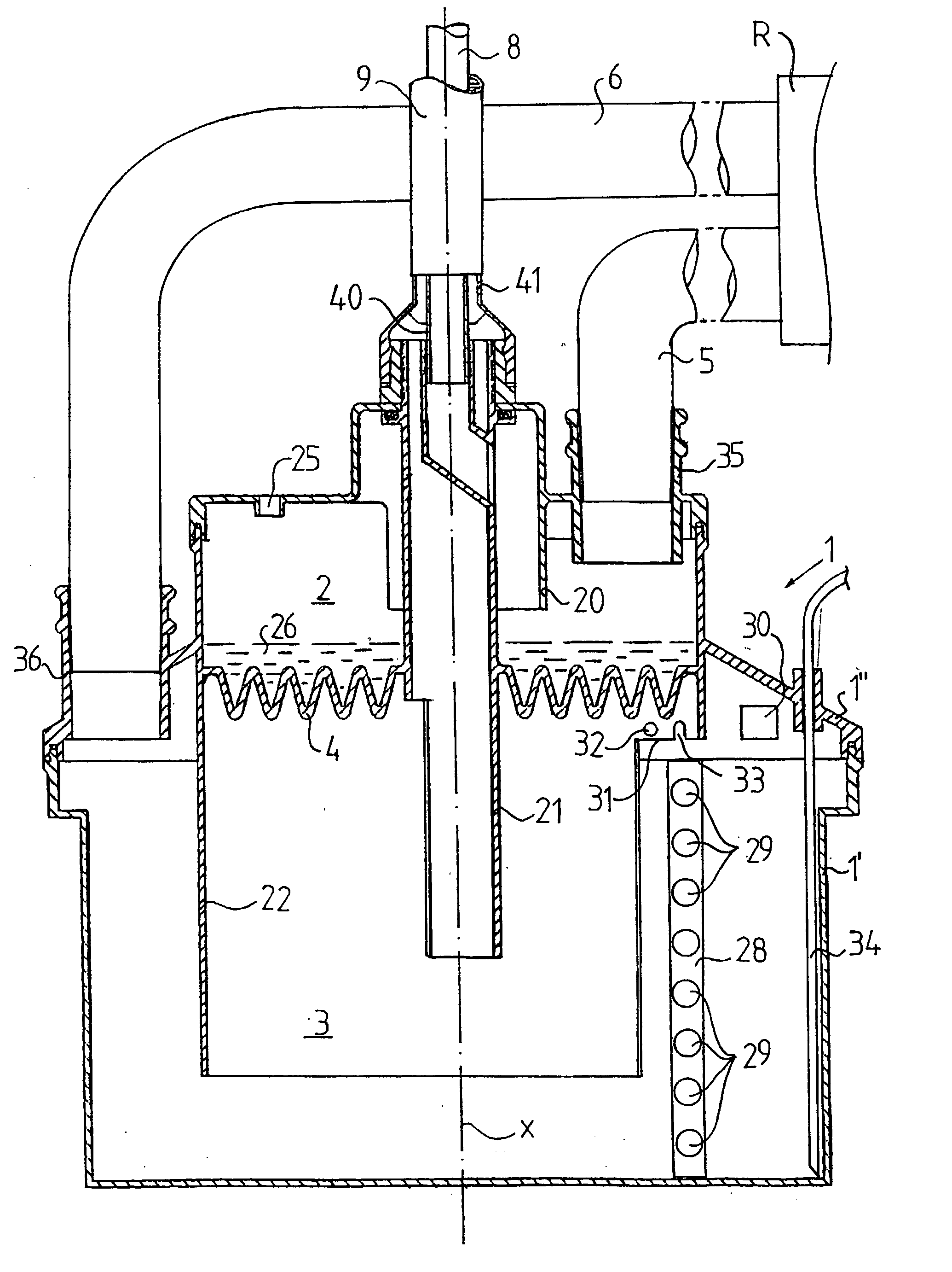
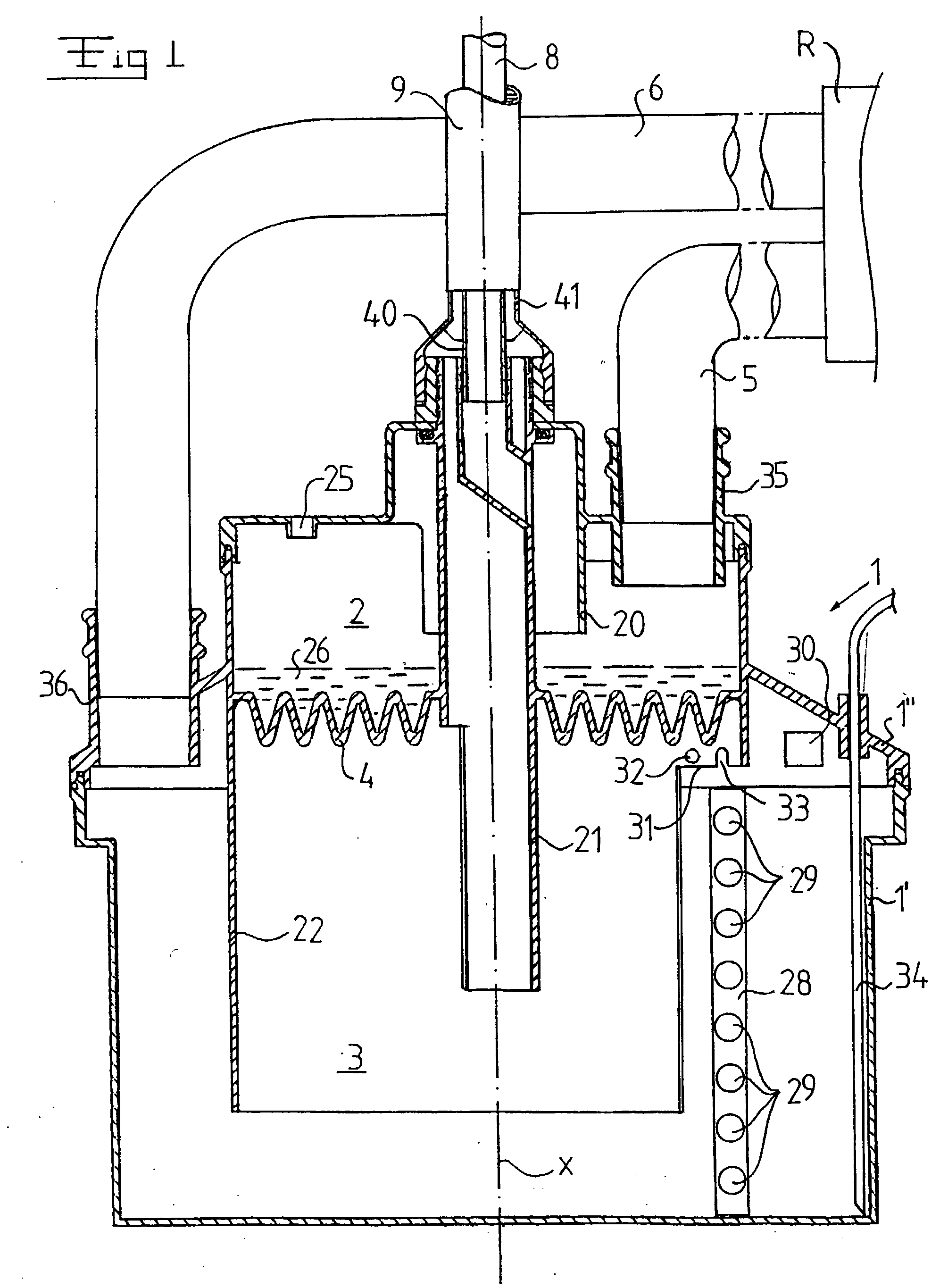
[0024] FIG. 1 discloses a container device 1, which encloses a first space 2 and a second space 3. The first space 2 is separated from the second space 3 by means of a wall member 4. The wall member 4 forms a bottom of the first space 2 and extends in a horizontal plane when the container device 1 is in an active state of use. The wall member 4 extends perpendicularly to a longitudinal axis x, which extends substantially vertically through the first space 2 and the second space 3 in said state of use.

[0025] The container device 1 is intended to be connected to a schematically indicated respirator R by means of a first external pipe conduit 5, which extends from the respirator R to the first space 2 for the supply of inhalation air to the first space 2. A container device 1 is also connected to the respirator R via a second external pipe conduit 6, which is connected to the second space 3 and arranged to permit removal of exhalation gas from the second space 3.

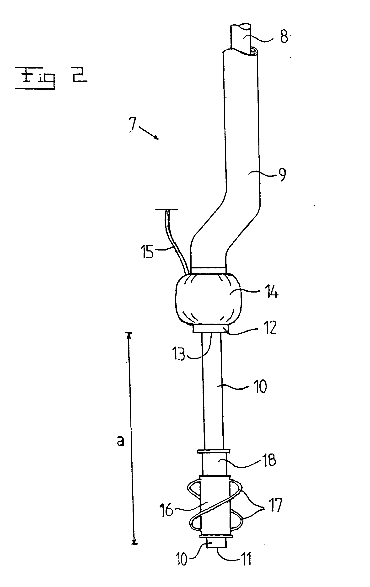
[0026] Furthermore, the...


PUM


Abstract

The invention refers to a device for collecting liquid from exhalation gas from a patient. The device includes a first pipe conduit (5, 8) for the supply of inhalation gas to the patient, a second pipe conduit (6, 9) for the removal of exhalation gas from the patient and a container device (1) for collecting liquid from the exhalation gas. The container device includes a first space (2), which forms a portion of the first pipe conduit (5, 8) and through which the inhalation gas thus flows, and a second space (3), which forms a portion of the second pipe conduit (6, 9) and through which the exhalation gas thus flows. The second space (3) is arranged to receive the collected liquid. The first space (2) is separated from the second space (3) by means of a wall member (4), which has a good thermal conductivity and permits transfer of heat from the exhalation gas to the inhalation gas.

Description

THE BACKGROUND OF THE INVENTION AND PRIOR ART[0001] The present invention refers to a device for collecting liquid from exhalation gas from a patient.[0002] The introduction of such devices for the supply of inhalation gas and the removal of exhalation gas, so called intubation, is made as a matter of routine in medical treatment of patients which need external breath support from a respirator. Such devices normally include a plastic pipe, a so called endotracheal tube, which via the throat is guided down into the trachea to a position at the dividing region of the main bronchi. The endotracheal tube is fixed in the trachea by means of a fixing member which is provided slightly above the distal end of the tube and inflated to airtight abutment against the inner wall of the trachea. Air exchange, i.e. supply of relatively oxygen-rich inhalation gas and removal of exhalation gas, takes place through one single channel in the tube, which via an external manifold is connected to the sup...

Claims


Application Information

Patent Timeline
IPC IPC(8): A61M1/00A61M16/00A61M16/08A61M16/16
CPCA61M16/0808
Inventor FLODIN, BJ?OUML, RN
Owner ALORO MEDICAL
Why Eureka
Try Eureka