Virtual private network over asynchronous transfer mode

a virtual private network and transfer mode technology, applied in the field of data communication networks, can solve the problems of one connection for each destination, network becomes very difficult to administer, and network is quickly overloaded with many independent connections

Inactive Publication Date: 2003-01-23
SBC TECH RESOURCES
View PDF72 Cites 77 Cited by
  • Summary
  • Abstract
  • Description
  • Claims
  • Application Information

AI Technical Summary

Problems solved by technology

However, U.S. Pat. No. 6,141,339 has a major disadvantage in that it requires one connection for each destination.
As a result, the network is quickly overburdened with many independent connections.
Furthermore, the network becomes very difficult to administer.
When enterprise data networks are added as possible destinations, how...

Method used


Image

  • Virtual private network over asynchronous transfer mode
  • Virtual private network over asynchronous transfer mode
  • Virtual private network over asynchronous transfer mode

Examples


first embodiment

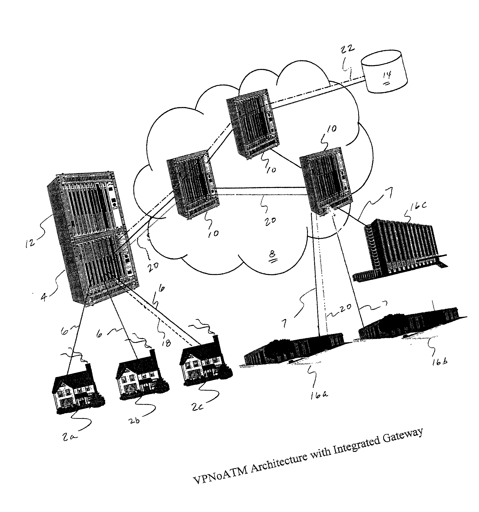
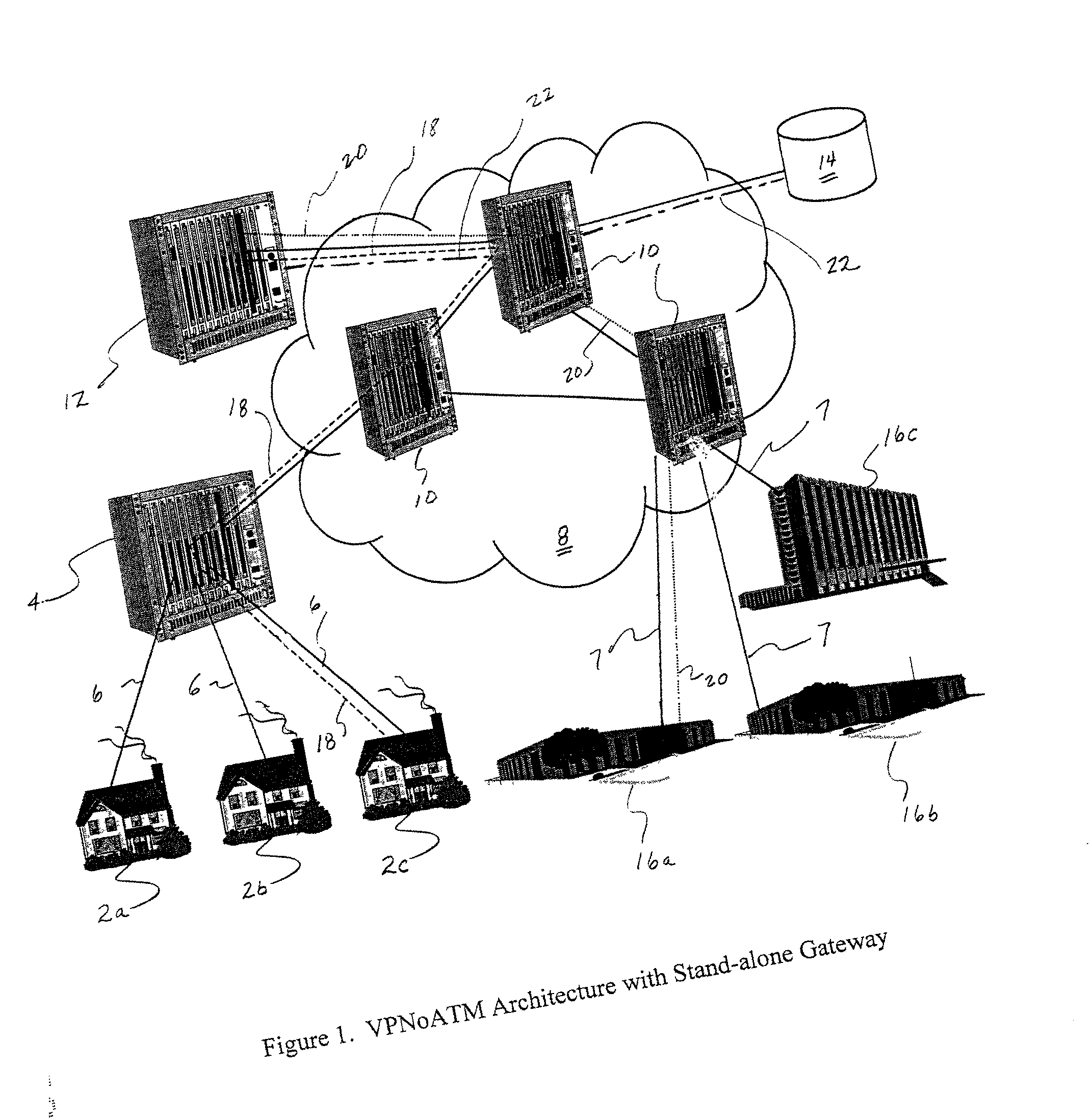
[0068] FIG. 1 illustrates the present invention. Broadband service subscribers 2a-c providing their own customer premises equipment (CPE), such as computers, are connected to an access multiplexer 4 in their neighborhood with high-speed access lines 6, such as xDSL. For sake of explanation, ADSL will be used throughout the remainder of the specification, however, the present invention is not limited to use of ADSL.

[0069] An ADSL modem (not shown), which utilizes Ethernet protocol or any other acceptable protocol, is utilized as an interface between the subscriber's CPE 2a-c and the ADSL access line. For instance, a customer's computer can be connected to the ADSL modem via an Ethernet cable, though USB versions of modems may also be used. The subscribers can provide their own ADSL modem, but typically the carrier provides an ADSL modem.

[0070] The access multiplexer 4 is connected to an ATM backbone network 8, including one or more ATM switches 10 that support both permanent virtual ...

second embodiment

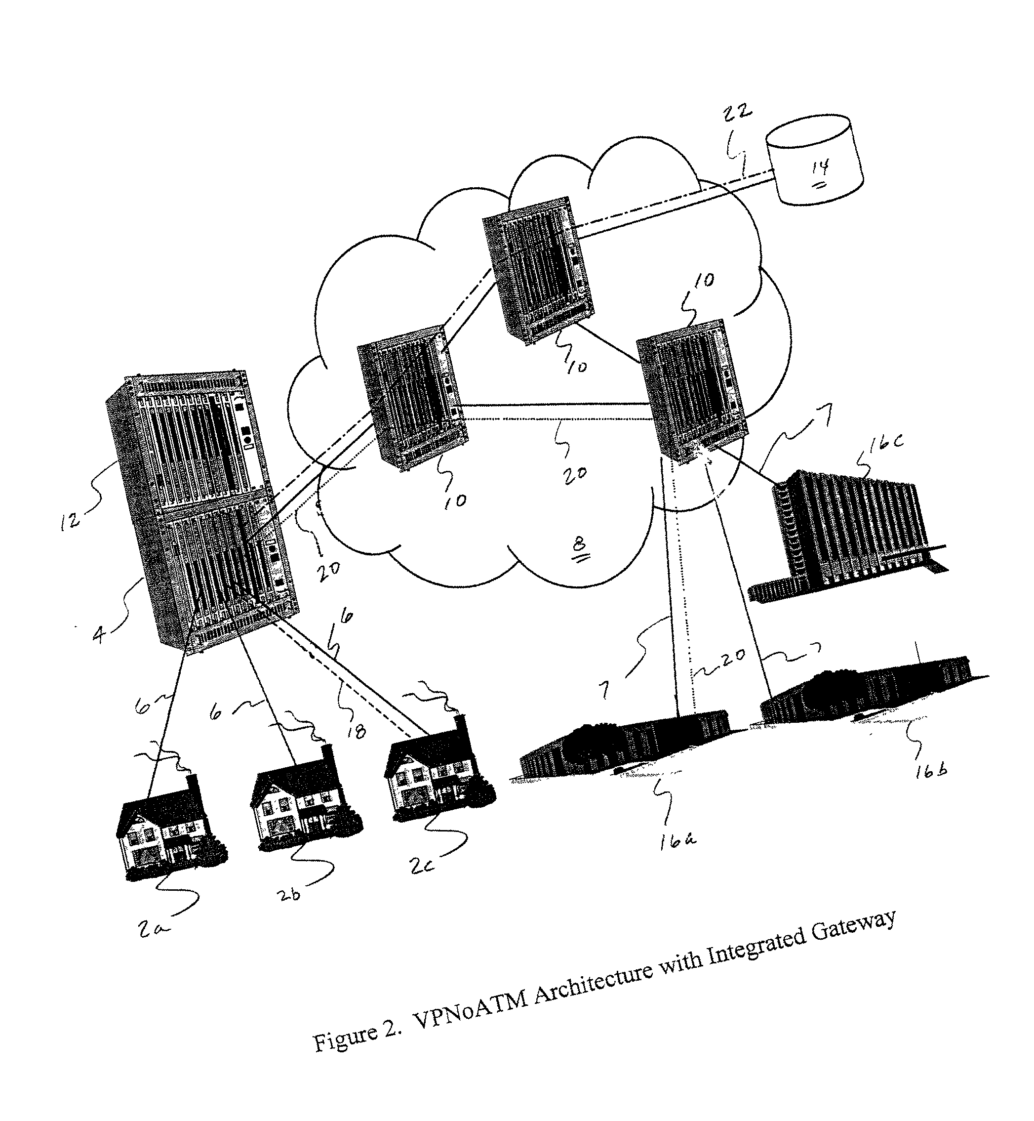
[0071] While the carrier's broadband service gateway 4 is shown in FIG. 1 as a separate piece of equipment, it can be integrated with either the access multiplexer 12 or the ATM switches 10. FIG. 2 illustrates the present invention in which the access multiplexer 4 and broadband service gateway 12 are integrated together.

[0072] Broadband access multiplexers 4, such the Alcatel ASAM 1000 and ASAM 7300, and ATM switches 10, such as the Alcatel 7670, Lucent GX 500 and CBX 550, capable of supporting both PVCs and SVCs are widely available. Broadband service gateways 12, such as the Nortel BSN-5000 are also available. Finally, IP routers such as the Cisco 3600, 6400, 7200 and 7500, are capable of terminating ATM SVCs are also currently available.

[0073] Directory servers 14, such as those using the Lightweight Directory Access Protocol (LDAP) and software capable of being run on a general-purpose computer are also commonly available. LDAP is a likely choice for implementation of the direc...


PUM


Abstract

A communications network and method enable broadband service subscribers to dynamically select broadband service destinations they wish to access from subscriber customer premises equipment. The communications network is an ATM network including a plurality of ATM switches. The network also includes at least one directory server connected to the ATM network, at least one fiber terminating device connected to the at least one directory server, and at least one broadband destination connected to the ATM network. Furthermore, the subscribers' customer premise equipment is connected to the at least one fiber terminating device. The method includes receiving a session request, which identifies a destination, in the at least one service gateway, wherein the session request is transmitted over a broadband connection using an Internet protocol. Next, using the at least one service gateway, an ATM network address of the destination from the at least one directory server is retrieved. Then an SVC is launched over the ATM network from the at least one service gateway to connect the subscriber to the ATM network address. Finally, the subsequent packets are forwarded to the destination over the ATM SVC connection.

Description

[0001] 1. Field of the Invention[0002] The present invention relates to a data communications network. In particular, the present invention discloses a technique for utilizing ATM SVCs (Asynchronous Transfer Mode Switched Virtual Circuits) to enable broadband service subscribers to dynamically choose the broadband destinations they wish to access in a manner that does not cause undue administrative overhead to the network carrier or broadband destination provider.[0003] 2. Acronyms[0004] The written description provided herein contains acronyms which refer to various telecommunications services, components and techniques, as well as features relating to the present invention. Although some of these acronyms are known, use of these acronyms is not strictly standardized in the art. For purposes of the written description herein, the acronyms are defined as follows:[0005] ADSL Transmission Unit-Remote (ATU-R)[0006] Asynchronous Transfer Mode Switched Virtual Circuit (ATM SVC)[0007] Cus...

Claims


Application Information

Patent Timeline
IPC IPC(8): H04L12/56H04Q11/04
CPCH04L2012/563H04L2012/5667H04Q11/0478
Inventor ALLEN, KEITH JOSEPHCHEN, WEIJINGSALGUERO, ANNA
Owner SBC TECH RESOURCES
Why Eureka
Try Eureka